In practice, two-input XOR elements are most often used. On fig. 1 shows the conditional graphic designation of the element without inversion and its state table. In simple terms, the essence of this element is as follows, the output signal appears only when the logical levels at the inputs are not the same.
Scheme of selection of the front and cutoff of the pulse
In this circuit, three XOR elements are used to delay the pulses. DD1.4 - summing. The output pulses have stable rising and falling edges. The duration of each output pulse is equal to three times the switching delay time of each of the three elements. The time interval between the fronts of the output pulses is equal to the duration of the input pulse. This device also doubles the frequency of the input signal.

There is another interesting property "XOR". If a constant “0” is applied to one of the inputs, then the signal at the output of the element will repeat the input signal, and if the constant “0” is changed to a constant “1”, then the output signal will already be the inversion of the input.
Sometimes it becomes necessary to obtain an XOR element from separate standard logical elements. An example is the XOR element circuit implemented on four 2-AND-NOT elements. Figure 3 shows the XOR circuit in its four states. This shows all possible logic levels on each of the 2-NAND gates used.

Such elements are included in the scheme. In this circuit, the XOR element is made on four 2-AND-NOT elements included in one housing of the K561LA7 microcircuit.
Discrete signal shaper with difference frequency
The shaper circuit is shown in Figure 4. Here logical element"XOR" is also implemented on four 2-AND-NOT elements. 
At the inputs 1 and 2 of the shaper, rectangular pulses fall (see graphs 1 and 2), which differ in repetition rate. The node on the logical elements DD1.1-DDI.4 multiplies these signals. The output pulse signal (graph 3) from the element DD1.4 is fed to the integrating circuit R3, C1, which converts it into a triangular signal (graph 4) with a frequency equal to the frequency difference of the input signals, and the op amp DA1 converts the received signal into a meander (see Fig. graph 5). Resistor R1 regulates the duration of the positive and negative half-waves of the output signal. A very interesting scheme. Radio designer, there is something to think about. For example, the signal shown in the third graph is a PWM sine wave signal.
Of course, the range of use of XOR elements is much wider. I brought here in my opinion more interesting for radio amateurs.
| Operator | Syntax | Description |
| AND | A AND B | Conjunction: If A and B are True, then True. Otherwise - False |
| OR | A OR B | Disjunction: If either operand is True, then True. Otherwise - False |
| NOT | NOT A | Negation: If A is False, then True. Otherwise - False |
| XOR | A XOR B | Exception: If A is True or B is True, then True. Otherwise - False |
| EQV | A EQV B | Equivalence: If A has the same value as B, then True. Otherwise - False |
| IMP | A IMP B | Implication: If A is True and B is False, then False. Otherwise - True |
As an operand for a logical operator, you can use any valid expression that has a Boolean result, as well as a number that can be converted to a Boolean value.
The result of a logical operation is a value of type Boolean (or Null if at least one of the operands is Null).
Logical operator AND
Syntax:
Operand_1 AND Operand_2
The AND operator performs logical conjunction.
The result of this operation is True only when both operands are True, otherwise False.
truth table
The AND operator can be used on multiple operands:
(5 3) AND (5=6) result is False
Regardless of the number of operands, the logical AND operation will result in True only if all operands of the expression evaluate to True. In any other case, the result will be False. Note that the operands are enclosed in parentheses. VBA first evaluates the value of each operand inside the brackets, and then the entire expression.
Logical operator OR
Syntax:
Operand_1 OR Operand_2
The OR operator performs logical disjunction.
The result of this operation is True if at least one of the operands is True, otherwise False.
truth table
The OR operator can be used on multiple operands:
(5 3) OR (5=6) result is True
Regardless of the number of operands, the result of the logical OR operation will always be True if at least one of the operands of the expression evaluates to True. Otherwise, the result will be False.
The AND and OR operators can be combined:
((5 3)) OR (5=6) result is True
Boolean operator NOT
Syntax:
NOT Operand
The NOT operator does logical negation.
The NOT operator uses only one operand.
truth table
AND OR NOT operators can be combined:
((5 3)) OR NOT (5=6) result is True
Logical operator XOR
Syntax:
Operand_1 XOR Operand_2
The XOR operator performs logical exception.
The result of this operation is True if the operands have different meanings, otherwise - False.
truth table
((5 3)) OR NOT (5=6) XOR (5=5) result is False
Logical operator EQV
Syntax:
Operand_1 EQV Operand_2
The EQV operator is the operator logical equivalence.
The result of this operation is True if the operands have the same value, otherwise False.
truth table
((5 3)) OR NOT (5=6) EQV (5=5) result is True
Boolean operator IMP
Syntax:
Operand_1 IMP Operand_2
The IMP statement performs a logical operation implications.
truth table
((5 3)) OR NOT (5=6) IMP (5=5) result is True
The IMP logical operator is the least intuitive of all logical operators. Fortunately, the need for its use arises quite rarely.
C++. logical operations. Bitwise logical operations. Shift operations. XOR operation
1. For what types can logical operations, bitwise logical operations and shift operations be used?
Logical operations, bitwise logical operations, and shift operations can only be used on operands of integer types.
2. What logical operations are used in C/C++?
The C/C++ programming language uses the following logical operations:
- && - logical "AND";
- || - logical "OR";
- ! - logical "NO".
The result of logical operations is either false or true . In the C++ language, false is considered to be 0 and true is considered to be 1.
From this we can conclude that false< true . Например:
// logical operations bool res; res=false< true ; // res = true3. Truth table of logical operations
Truth table of logical operations && (logical "AND"), || (logical "OR"), ! (logical "NO") has the following form:
The C/C++ language assumes that false is 0 and true is not 0 (any non-zero integer value).
4. Examples of using logical operations in C++
Example 1 Boolean operation combined with a boolean expression
// logical operations bool res; int a, b; // operation && (AND) a = 8; b = 5; res = a && b; // res = True a = 0; res = a && b; // res = False // operation || (OR) a = 0; b = 0; res = a || b; // res = False b = 7; res = a || b; // res = True // operation! (logical "NO") a = 0; res = !a; // res = True a = 15; res = !a; // res = falseExample 2 Logical operation in conditional expressions. A code snippet is provided in which a logical operation is used in the if statement.
// logical operations in conditional expressions int a, b; bool res; a = 0; b = 3; res = false ; if (a && b) res = true ; // res = false a = 0; b = 7; if (a || b) res = true ; // res = true5. What bitwise logical operations are used in C/C++?
The C/C++ language supports the following bitwise logical operations:
- & - bitwise logical AND (AND);
- ^ – bitwise addition modulo 2 (XOR - exclusive OR);
- | - bitwise logical OR(OR);
- ~ – bitwise inversion (NOT).
Operations & , ^ , | are binary. This means that they require two operands. The bits of any operand are compared with each other according to the following rule: The bit at position 0 of the first operand is compared with the bit at position 0 of the second operand. The bit at position 1 of the first operand is then compared with the bit at position 1 of the second operand. This compares all bits of the integer operands.
6. Truth table of bitwise logical operations
Each bit of the result is determined based on two operands, which are bits as shown in the table.

The inversion requires a single operand to the right of the ~ sign. The result is obtained by bitwise inversion of all bits of the operand.
7. An example of working with logical bitwise operations
Let two numbers 17 and 45 of type unsigned short int be given. Each number occupies 1 byte or 8 bits in memory. The following is an example of how the calculation is done for each bitwise operation

As can be seen from the example, the specified operation is performed on each bit.
8. What shift operations are used in C/C++?
The C/C++ language includes two bitwise operations shear:
- << – left shift of the operand value by the specified number of bits. The operand is placed to the left of the sign of the operation. The number of bits to shift is indicated to the right of the sign of the operation;
- >> – right shift of the operand value by the specified number of bits. The operand is placed to the left of the sign of the operation (<<). The number of bits to shift is placed to the right of the sign of the operation.
Pull-out bits are lost and zero bits are "in". Shifting operands to the left by 1, 2, 3 or more places is the fastest way to multiply by 2, 4, 8, ... Shifting the operands to the right by 1, 2, 3 or more places is the fastest way to divide by 2, 4, 8, ...
If the program needs the operation of multiplying integer operands by 2, 4, 8, etc. occurred as quickly as possible, it is advisable to use the shift operation to the left.
This also applies to cases where you need to quickly divide an integer operand by 2, 4, 8, etc. In these cases, it is recommended to use shift to the right.
9. Examples of using shift operations in a program
// Shift operations int a; intb; int c; a = 15; b = -5; // shift left - multiplication c = a<< 1; // c = a * 2^1 = 30 c = b << 2; // c = b * 2^2 = -20 // shift right - division c = a >> 3; // c = a / 2^3 = 1 c = b >> 1; // c = b / 2^1 = -310. What is the difference between logical operations and bitwise logical operations?
In logical operations, the entire value of two operands is compared. Each of the operands can be either true or false . The C/C++ language allows comparison of operands that are integers. In this case, an integer value of 0 corresponds to false , and a nonzero (any other) value corresponds to true .
Behavior
Elements XOR, XOR-NOT, Odd and Even calculate the corresponding function from the values at the inputs and give the result to the output.
By default, unconnected inputs are ignored - that is, if the inputs really don't have anything connected to them - not even wires. So you can add a 5-input element but only connect two inputs and it will work like a 2-input element; this saves you from having to worry about setting the number of inputs every time you create an element. (If all inputs are not connected, then the output error value X.) Some users, however, prefer Logisim to insist that all inputs are connected, as this matches the real elements. You can enable this behavior by selecting the menu Project > Options…, going to the Simulation tab, and selecting the Error for Undefined Inputs option for Element Output on Uncertainty.
The two-input truth table for elements is as follows.
| x | y | XOR | Exclusive NOR | odd | Parity |
|---|---|---|---|---|---|
| 0 | 0 | 0 | 1 | 0 | 1 |
| 0 | 1 | 1 | 0 | 1 | 0 |
| 1 | 0 | 1 | 0 | 1 | 0 |
| 1 | 1 | 0 | 1 | 0 | 1 |
As you can see, the Odd and XOR elements behave the same in the case of two inputs; similarly, the Parity and XOR elements behave the same. But if there are more than two inputs with a certain value, then the XOR element will output 1 when the unit is strictly on one input, while the Odd element will output 1 when the unit is on an odd number of inputs. The XOR element will produce an output of 1 when inputs with a unit are strictly not one, while the Parity element will give 1 when there are an even number of inputs with one. The XOR and XOR elements have an attribute called Multi-Input Behavior that allows you to configure them to use the behavior of the Odd and Even elements.
If any inputs have an error value (for example, if conflicting values are on the same wire) or a floating value, then the output will be an error value.
The multi-bit versions of each element will perform their one-bit conversions on the inputs bit by bit.
Note: many experts argue that the behavior of the curly element XOR should correspond to the behavior of the element Odd, but there is no agreement on this issue. Logisim's default behavior for the XOR element is based on the IEEE 91 standard. This is also consistent with the intuitive understanding of the term XOR: A waiter asking if you would like a side dish of mashed potatoes, carrots, green peas, or slaw will only accept one choice, not three, regardless of what some experts may tell you. (I must admit, however, that I haven't put this statement to the test.) You can set the XOR and XOR elements to use one of the options by changing its Multi-Input Behavior attribute.
Contacts (assuming the component is facing east)
West edge (inputs, bit width matches Data Bits attribute)Component inputs. There will be as many of them as specified in the Number of inputs attribute.
Note that if you use curly elements, then the western edge of the XOR and XOR elements will be curved. However, the input pins are spaced hardly. Logisim draws short segments to show this; if you overlap a segment, the program will silently assume that you didn't mean to overlap it. When using "Print View", these segments will not be drawn unless connected to wires.
East edge (output, bit width matches Data Bits attribute)
The output of an element whose value is calculated based on the current values of the inputs, as described above.
Attributes
When a component is selected, or already added, keys 0 to 9 change its Number of Inputs attribute, combinations Alt-0 to Alt-9 change its Data Bits attribute, and arrow keys change its Direction attribute.
Direction The direction of the component (its output relative to its inputs). Data bits The bits of the inputs and outputs of the component. Element Size Specifies whether to render the wide or narrow version of the component. This does not affect the number of entries, which is determined by the Number of entries attribute; however, if the number of inputs exceeds 3 (for a narrow component) or 5 (for a wide component), then the element will be rendered with "wings" to accommodate the requested number of inputs. Number of Inputs Determines how many pins on the west edge the component will have. Multi-input Behavior (XOR and XOR-NOT only) When there are three or more inputs, the output value of the XOR and XOR-NOR elements will either be based on the fact that 1 is strictly on one input (default), or on an odd number of inputs.
An electrical circuit designed to perform any logical operation on input data is called a logic element. The input data is represented here in the form of voltages of various levels, and the result of a logical operation at the output is also obtained in the form of a voltage of a certain level.
Operands in this case are fed - signals are received at the input of the logic element in the form of a high or low level voltage, which essentially serve as input data. So, a high-level voltage - a logical one - indicates the true value of the operand, and a low-level voltage of 0 - a false value. 1 - TRUE, 0 - FALSE.
Logic element- an element that implements certain logical relationships between input and output signals. Logic gates are commonly used to build logic circuits computers, discrete circuits of automatic control and management. For all types of logical elements, regardless of their physical nature, discrete values of input and output signals are characteristic.
Logic elements have one or more inputs and one or two (usually inverse to each other) outputs. The values of "zeros" and "ones" of the output signals of logical elements are determined by the logical function that the element performs, and the values of "zeros" and "ones" of the input signals, which play the role of independent variables. There are elementary logical functions from which any complex logical function can be composed.
Depending on the device of the element circuit, on its electrical parameters, the logic levels (high and low voltage levels) of the input and output have the same values for high and low (true and false) states.
Traditionally, logic elements are produced in the form of special radio components - integrated circuits. Logical operations such as conjunction, disjunction, negation and modulo addition (AND, OR, NOT, exclusive OR) are the main operations performed on logical elements of basic types. Let's take a closer look at each of these types of logical elements.
Logical element "AND" - conjunction, logical multiplication, AND

"AND" - a logical element that performs a conjunction or logical multiplication operation on the input data. This element can have from 2 to 8 (the most common in production are “AND” elements with 2, 3, 4 and 8 inputs) inputs and one output.
Symbols of logical elements "AND" with a different number of inputs are shown in the figure. In the text, the logical element "AND" with one or another number of inputs is designated as "2I", "4I", etc. - the element "AND" with two inputs, with four inputs, etc.
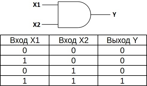
The truth table for the element 2I shows that the output of the element will be a logical unit only if the logical ones are simultaneously at the first input AND at the second input. In the other three possible cases the output will be zero.
In Western schemes, the icon of the "And" element has a straight line at the entrance and a rounding at the exit. On domestic schemes - a rectangle with the symbol "&".
Logical element "OR" - disjunction, logical addition, OR

"OR" - a logical element that performs a disjunction or logical addition operation on the input data. It, like the “AND” element, is available with two, three, four, etc. inputs and one output. Symbols of logical elements "OR" with a different number of inputs are shown in the figure. These elements are designated as follows: 2OR, 3OR, 4OR, etc.

The truth table for the element "2OR" shows that for the appearance of a logical unit at the output, it is enough that the logical unit is at the first input OR at the second input. If logical ones are at once on two inputs, the output will also be one.
In Western schemes, the icon for the "OR" element has a rounded entry and a rounded, pointed exit. On domestic schemes - a rectangle with the symbol "1".
Logic element "NOT" - negation, inverter, NOT
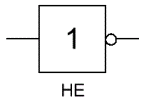
"NOT" - a logical element that performs a logical negation operation on the input data. This element, which has one output and only one input, is also called an inverter, since it actually inverts (inverts) the input signal. The figure shows symbol logical element "NOT".

The truth table for the inverter shows that a high input potential gives a low output potential and vice versa.
In Western schemes, the icon of the "NOT" element has the shape of a triangle with a circle at the exit. On domestic schemes - a rectangle with the symbol "1", with a circle at the exit.
Logical element "AND-NOT" - conjunction (logical multiplication) with negation, NAND

"AND-NOT" - a logical element that performs a logical addition operation on the input data, and then a logical negation operation, the result is output. In other words, it is basically an "AND" element, complemented by a "NOT" element. The figure shows the symbol of the logical element "2I-NOT".

The truth table for the "NAND" element is the opposite of the table for the "AND" element. Instead of three zeros and one - three ones and zero. The "NAND" element is also called the "Schaeffer element" in honor of the mathematician Henry Maurice Schaeffer, who first noted the significance of this in 1913. Designated as "I", only with a circle at the exit.
Logical element "OR-NOT" - disjunction (logical addition) with negation, NOR

"OR-NOT" - a logical element that performs a logical addition operation on the input data, and then a logical negation operation, the result is output. In other words, this is an "OR" element, supplemented by a "NOT" element - an inverter. The figure shows the symbol of the logic element "2OR-NOT".

The truth table for the element "OR-NOT" is opposite to the table for the element "OR". A high potential at the output is obtained only in one case - both inputs are fed simultaneously with low potentials. Referred to as "OR", only with a circle at the output indicating inversion.
Logical element "exclusive OR" - addition modulo 2, XOR

"XOR" - a logical element that performs the operation of logical addition modulo 2 on the input data, has two inputs and one output. Often these elements are used in control schemes. The figure shows the symbol of this element.
The image in Western schemes is like that of "OR" with an additional curved strip on the input side, in the domestic one - like "OR", only instead of "1" it will be written "=1".

This logical element is also called "inequivalence". High level voltage will be at the output only when the signals at the input are not equal (on one unit, on the other zero or on one zero, and on the other one) even if there are two units at the input at the same time, the output will be zero - this is the difference from " OR". These logic elements are widely used in adders.