Availability and relatively low prices for super-bright light-emitting diodes (LED) allow them to be used in various amateur devices. Beginning radio amateurs who use LED for the first time in their designs often wonder how to connect an LED to a battery? After reading this material, the reader will learn how to light an LED from almost any battery, what LED connection schemes can be used in a particular case, how to calculate circuit elements.
In principle, you can simply light the LED from any battery. Designed by radio amateurs and professionals electronic circuits enable them to successfully accomplish this task. Another thing is how long the circuit will work continuously with a specific LED (LEDs) and a specific battery or batteries.
To estimate this time, you should know that one of the main characteristics of any battery, whether it is a chemical element or a battery, is its capacity. Battery capacity - C is expressed in ampere-hours. For example, the capacity of common AAA finger batteries, depending on the type and manufacturer, can be from 0.5 to 2.5 ampere-hours. In turn, light-emitting diodes are characterized by a working current, which can be tens and hundreds of milliamps. Thus, you can approximately calculate how long the battery lasts using the formula:
T= (C*U baht)/(U work led *I work led)
In this formula, the numerator is the work that the battery can do, and the denominator is the power consumed by the light emitting diode. The formula does not take into account the efficiency of a particular circuit and the fact that it is extremely problematic to fully use the entire battery capacity.
When designing battery-powered devices, they usually try to ensure that their current consumption does not exceed 10 - 30% of the battery capacity. Guided by this consideration and the above formula, you can estimate how many batteries of a given capacity are needed to power a particular LED.
How to connect from a 1.5V AA battery

Unfortunately does not exist easy way power the LED from one AA battery. The fact is that the operating voltage of light emitting diodes usually exceeds 1.5 V. For this value, this value lies in the range of 3.2 - 3.4V. Therefore, to power the LED from one battery, you will need to assemble a voltage converter. Below is a diagram of a simple voltage converter on two transistors with which you can power 1 - 2 super-bright LEDs with a working current of 20 milliamps.

This converter is a blocking oscillator assembled on a transistor VT2, a transformer T1 and a resistor R1. The blocking generator generates voltage pulses that are several times higher than the voltage of the power source. Diode VD1 rectifies these pulses. Inductor L1, capacitors C2 and C3 are elements of the smoothing filter.
Transistor VT1, resistor R2 and zener diode VD2 are elements of a voltage regulator. When the voltage across capacitor C2 exceeds 3.3 V, the zener diode opens and a voltage drop is created across resistor R2. At the same time, the first transistor will open and lock VT2, the blocking generator will stop working. Thus, the output voltage of the converter is stabilized at the level of 3.3 V.
As VD1, it is better to use Schottky diodes, which have a low voltage drop in the open state.
Transformer T1 can be wound on a 2000NN grade ferrite ring. The diameter of the ring can be 7 - 15 mm. As a core, you can use rings from converters of energy-saving light bulbs, filter coils of computer power supplies, etc. The windings are made with enameled wire with a diameter of 0.3 mm, 25 turns each.
This scheme can be painlessly simplified by eliminating the stabilization elements. In principle, the circuit can do without a choke and one of the capacitors C2 or C3. Even a novice radio amateur can assemble a simplified circuit with his own hands.

The circuit is also good because it will work continuously until the power supply voltage drops to 0.8 V.
How to connect from a 3V battery
You can connect a super-bright LED to a 3V battery without using any additional parts. Since the operating voltage of the LED is slightly more than 3 V, the LED will not shine at full strength. Sometimes it can even be helpful. For example, using an LED with a switch and a 3V disk battery (popularly called a coin cell) used in motherboards computer, you can make a small flashlight keychain. Such a miniature flashlight can be useful in different situations.

From such a battery - 3 Volt tablets you can power the LED
Using a couple of 1.5 V batteries and a commercial or homemade converter to power one or more LEDs, you can make a more serious design. A diagram of one of these converters (boosters) is shown in the figure.

The booster based on the LM3410 chip and several attachments has the following characteristics:
- input voltage 2.7 - 5.5 V.
- maximum output current up to 2.4 A.
- number of connected LEDs from 1 to 5.
- conversion frequency from 0.8 to 1.6 MHz.
The output current of the converter can be adjusted by changing the resistance of the measuring resistor R1. Despite the fact that it follows from the technical documentation that the microcircuit is designed to connect 5 LEDs, in fact, 6 can be connected to it. This is due to the fact that the maximum output voltage chip 24 V. Another LM3410 allows the glow of LEDs (dimming). For these purposes, the fourth output of the microcircuit (DIMM) is used. Dimming can be done by changing the input current of this pin.
How to connect from a 9V Krona battery
"Krona" has a relatively small capacity and is not very suitable for powering high-power LEDs. The maximum current of such a battery should not exceed 30 - 40 mA. Therefore, it is better to connect 3 light-emitting diodes connected in series with an operating current of 20 mA to it. They, as in the case of connecting to a 3 volt battery, will not shine at full strength, but on the other hand, the battery will last longer.

Krona battery power scheme

In one material it is difficult to cover all the variety of ways to connect LEDs to batteries with different voltages and capacities. We tried to talk about the most reliable and simple designs. We hope that this material will be useful for both beginners and more experienced radio amateurs.
Weather stations on .
After thinking, I came to the conclusion that the most expensive and voluminous part of the weather station is the board Arduino Uno. The cheapest replacement option would be the Arduino Pro Mini board. The Arduino Pro Mini board comes in four variants. To solve my problem, a variant with a Mega328P microcontroller and a supply voltage of 5 volts is suitable. But there is another option for a voltage of 3.3 volts. How are these options different? Let's figure it out. The fact is that an economical voltage regulator is installed on the Arduino Pro Mini boards. For example, such as MIC5205 with an output voltage of 5 volts. These 5 volts are applied to the Vcc pin. arduino boards Pro Mini, so the board will be called "Arduino Pro Mini Board with 5 Volts". And if another chip with an output voltage of 3.3 volts is supplied instead of the MIC5205 chip, then the board will be called "Arduino Pro Mini board with a supply voltage of 3.3 volts"
The Arduino Pro Mini can be powered by an external unregulated power supply up to 12 volts. This power must be supplied to the RAW pin of the Arduino Pro Mini. But after looking at the datasheet technical document) to the MIC5205 chip, I saw that the range of power supplied to the Arduino Pro Mini board could be wider. Unless, of course, the MIC5205 chip is on the board.
Datasheet on the MIC5205 chip:

The input voltage applied to the MIC5205 chip can be from 2.5 volts to 16 volts. In this case, the output of the standard switching circuit should have a voltage of about 5 volts without the declared accuracy of 1%. If we use the information from the datasheet: VIN = VOUT + 1V to 16V (Vin = Vout + 1V to 16V) and taking Vout for 5 volts, we get that the supply voltage of the Arduino Pro Mini board supplied to the RAW pin can be from 6 volts up to 16 volts with an accuracy of 1%.
Datasheet for the MIC5205 chip:
To power the GY-BMP280-3.3 board for measuring barometric pressure and temperature, I want to use a module with an AMS1117-3.3 chip. The AMS1117 is a low dropout linear voltage regulator.
Photo module with AMS1117-3.3 chip:


Datasheets for the AMS1117 chip:
Module diagram with AMS1117-3.3 chip:

I indicated on the module diagram with the AMS1117-3.3 chip the input voltage from 6.5 volts to 12 volts, basing this on the documentation for the AMS1117 chip.

The seller specifies an input voltage of 4.5 volts to 7 volts. The most interesting thing is that another seller on Aliexpress.com indicates a different voltage range - from 4.2 volts to 10 volts.

What's the matter? I think that manufacturers solder capacitors into the input circuits with a maximum allowable voltage less than the parameters of the microcircuit allow - 7 volts, 10 volts. And, perhaps, they even install defective microcircuits with a limited range of supply voltages. I don’t know what will happen if the board with the AMS1117-3.3 chip I bought is supplied with 12 volts.
Perhaps, to improve the reliability of the Chinese board with the AMS1117-3.3 chip, it will be necessary to change ceramic capacitors to electrolytic tantalum capacitors. Such a switching scheme is recommended by the manufacturer of AMS1117A microcircuits, the Minsk plant of the Transistor Plant Unitary Enterprise.
From different computer boards, I sometimes use them to stabilize required voltages in chargers from cell phones. And recently, I needed a portable and compact power supply unit for 4.2 V 0.5 A to check phones with rechargeable batteries, and I did this - I took a suitable charge, added a stabilizer scarf based on this microcircuit, it works fine.

And for general development detailed information about this series. The APL1117 is a positive polarity linear voltage regulator with low saturation voltage, available in SOT-223 and ID-Pack packages. Available for fixed voltages of 1.2, 1.5, 1.8, 2.5, 2.85, 3.3, 5.0 volts and 1.25 V adjustable.

The output current of microcircuits is up to 1 A, the maximum power dissipation is 0.8 W for microcircuits in the SOT-223 package and 1.5 W in the D-Pack package. There is a protection system for temperature and power dissipation. A strip of copper foil can be used as a radiator printed circuit board, small plate. The microcircuit is attached to the heat sink by soldering a heat-conducting flange or glued to the body and flange using heat-conducting glue.

The use of microcircuits of these series provides increased output voltage stability (up to 1%), low current and voltage instability coefficients (less than 10 mV), higher efficiency than conventional 78LXX, which allows to reduce input supply voltages. This is especially true when powered by batteries.

If a more powerful stabilizer is required that delivers a current of 2-3 A, then the typical circuit must be changed by adding a transistor VT1 and a resistor R1 to it.
Stabilizer on the AMS1117 chip with a transistor

The KT818 series transistor in a metal case dissipates up to 3 watts. If more power is required, then the transistor should be installed on a heat sink. With this inclusion, the maximum load current for KT818BM can be up to 12 A. The author of the project is Igoran.
Discuss the article MINIATURE VOLTAGE REGULATORS
The basis of the voltage stabilizer (see Fig. 1) is the K157XP2 microcircuit. A wonderful and not justly forgotten stabilizer, with an additional transistor, for example, KT972A, can operate with current up to 4A.
In this circuit, the output voltage of the stabilizer is 3V. The stabilizer is designed to power low-voltage radio equipment. In general, with the resistor values indicated in the diagram, the output voltage can be set from 1.3 to 6V. For high load currents, the transistor must be installed on a suitable heatsink. The input voltage supplied to the stabilizer must be at least seven volts, although in practice it can be up to forty. Such a stabilizer works well from a car battery. The main thing is that the power released on the transistor does not exceed the maximum allowable 8W. Switch SB1 can switch the output voltage. With high load currents, this is very convenient - it is possible to use low-power toggle switches.
How to get a non-standard voltage that does not fit into the standard voltage range?
The standard voltage is the voltage that is very often used in your electronic gadgets. This voltage is 1.5 Volts, 3 Volts, 5 Volts, 9 Volts, 12 Volts, 24 Volts, etc. For example, your antediluvian MP3 player contained one 1.5 volt battery. On the remote remote control TV already uses two batteries of 1.5 Volts, connected in series, which means already 3 Volts. The USB connector has the most extreme contacts with a potential of 5 volts. Probably everyone had Dandy in their childhood? To power Dandy, it was necessary to apply a voltage of 9 volts to it. Well 12 volts is used in almost all cars. 24 volts is already used mainly in industry. Also, for this, relatively speaking, standard range, various consumers of this voltage are “sharpened”: light bulbs, players, and so on.
But, alas, our world is not perfect. Sometimes it’s just that you really need to get a voltage that is not from the standard range. For example, 9.6 volts. Well, neither way ... Yes, here the power supply helps us out. But then again, if you use a ready-made power supply, then you will have to carry it along with the electronic trinket. How to solve this issue? So, I will give you three options:
Option number 1
Make a voltage regulator in the electronic trinket circuit according to this scheme (in more detail):
Option number 2
On Three-terminal voltage stabilizers, build a stable source of non-standard voltage. Plans for the studio!

What do we see as a result? We see a voltage regulator and a zener diode connected to the middle output of the stabilizer. XX are the last two digits written on the stabilizer. There may be numbers 05, 09, 12, 15, 18, 24. Maybe there are even more than 24. I don’t know, I won’t lie. These last two numbers tell us about the voltage that the stabilizer will produce according to the classical switching scheme:
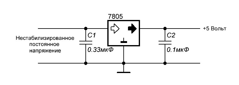
Here, the 7805 stabilizer gives us 5 volts at the output according to this scheme. The 7812 will put out 12 volts, the 7815 will put out 15 volts. You can read more about stabilizers.
U zener diode is the stabilization voltage at the zener diode. If we take a zener diode with a stabilization voltage of 3 Volts and a voltage stabilizer of 7805, then we get 8 Volts at the output. 8 Volts is already a non-standard voltage range ;-). It turns out that by choosing the right stabilizer and the right zener diode, you can easily get a very stable voltage from a non-standard range of voltages ;-).
Let's look at all this with an example. Since I'm just measuring the voltage at the terminals of the stabilizer, so I don't use capacitors. If I were powering the load, then I would use capacitors as well. Our guinea pig is the 7805 stabilizer. We feed 9 volts from the bulldozer to the input of this stabilizer:
Therefore, the output will be 5 volts, after all, after all, the 7805 stabilizer.

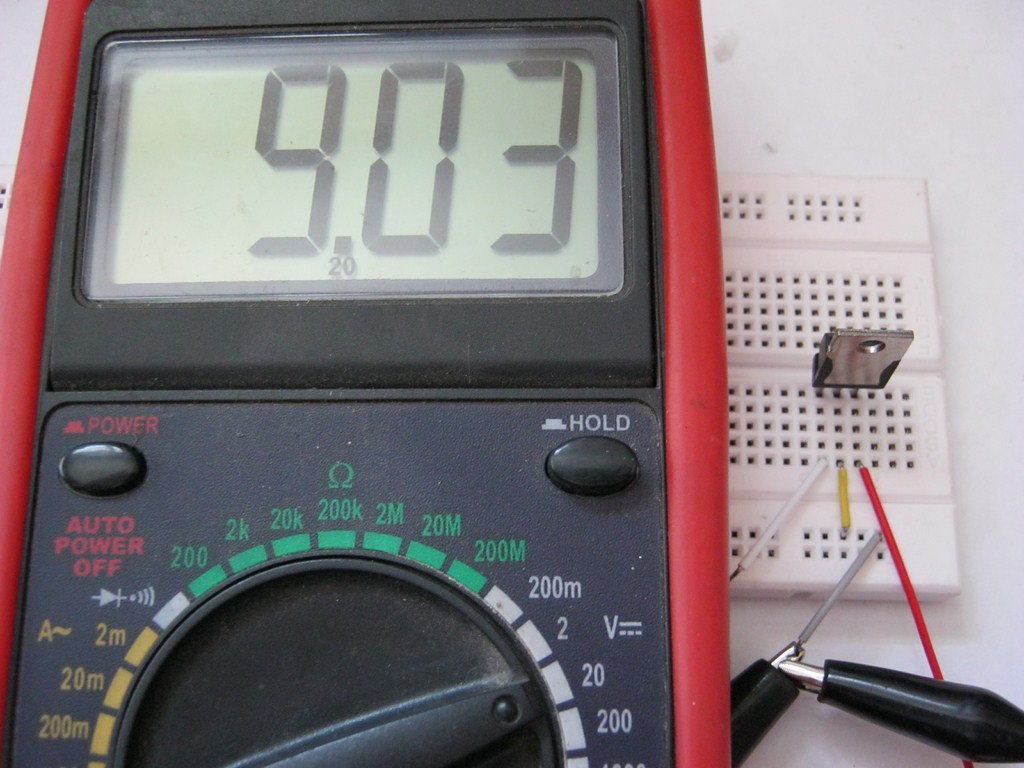
Now we take a zener diode for stabilization U \u003d 2.4 Volts and insert it according to this scheme, it is possible without capacitors, after all, we just do voltage measurements.

Whoa, 7.3 volts! 5 + 2.4 Volts. Works! Since my zener diodes are not high-precision (precision), the voltage of the zener diode may differ slightly from the passport voltage (voltage declared by the manufacturer). Well, I guess it's not a problem. 0.1 volts will not do the weather for us. As I said, in this way you can pick up any value out of the ordinary.
Option number 3
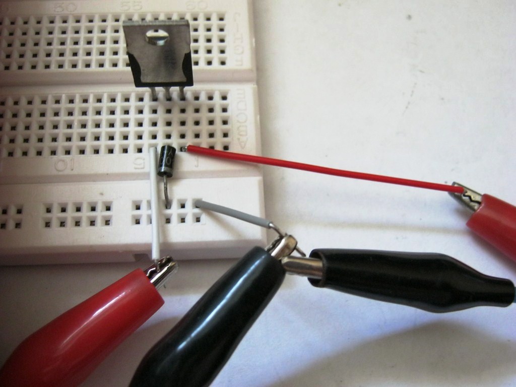
There is also another similar method, but diodes are used here. Maybe you know that the voltage drop at the direct junction of a silicon diode is 0.6-0.7 Volts, and a germanium diode is 0.3-0.4 Volts? It is this property of the diode that we will use ;-).
So, the scheme in the studio!

We assemble this design according to the scheme. The unstabilized input DC voltage also remained at 9 volts. Stabilizer 7805.
So what's the output?

Almost 5.7 Volts ;-), which was to be proved.
If two diodes are connected in series, then the voltage will drop across each of them, therefore, it will be summed up:

Each silicon diode drops 0.7 volts, which means 0.7 + 0.7 = 1.4 volts. Also with germanium. You can connect both three and four diodes, then you need to sum the voltages on each. In practice, more than three diodes are not used. Diodes can be installed even with low power, since in this case the current through them will still be small.