This article shows different options for controlling relays in arduino sketches. The examples were tested on the Arduino Uno, but they can be easily applied to other Arduino boards: Uno, Mega, Nano.
Wiring diagram
AT this example a standard one is used, on which all the necessary elements for connecting to are already installed. The connection diagram is very simple: the relay module is connected to pin 5 of the Arduino board. At the same time, for simplicity, we can not even connect a real load - the relay will click with each state change, we will hear these clicks and we will understand that the sketch is working.
Sketch for working with relays
/* * Sketch to control the relay using arduino * Use the SONGLE SRD-05VDC relay * The relay OPEN when the LOW signal is applied to the control pin. * Relay CLOSE when HIGH signal is applied to the control pin. * * In this example, we simply open and close the relay every 5 seconds. * * PIN_RELAY contains the pin number to which the relay is connected, which we will control * * In the setup function, set the initial position of the relay (closed) * If a load (for example, a light bulb) is connected to the relay, then after starting the sketch, it will turn on and off every 5 seconds * * To change the blinking period, you need to change the parameter of the delay() function: by setting 1000 milliseconds, you get 1 second of delay * * In real projects, the relay turns on in response to the detection of any external events through the connection of sensors * */ #define PIN_RELAY 5 // Define the pin used to connect the relay // In this function, define the initial settings void setup() ( pinMode(PIN_RELAY, OUTPUT); // Declare the relay pin as an output digitalWrite(PIN_RELAY, HIGH); // Turn off the relay - send high signal ) void loop() ( digitalWrite(PIN_RELAY, LOW); // Turn on the relay - send a low signal level delay(5000); digitalWrite(PIN_RELAY, HIGH); // Turn off the relay - send a high signal delay(5000); )Relay control sketch with motion sensor
In real projects, the change in the state of the relay should occur in response to some reaction of the environment. For example, in response to a signal from a triggered motion sensor, you can turn on the light by closing the circuit using a relay. In this sketch, we will consider such a connection option.
Relay connection diagram

It should be understood that in real projects they do without an arduino at all - simply by connecting the signal output of the sensor to the relay.
Sketch example
In this example, we will add a PIR status check to the loop using the digitalRead() function. If we get HIGH, then this means the sensor is triggered and we perform an action - turn on the relay. If you attach a light bulb to it, it will light up. But, as in the previous example, you can just listen for clicks.
/* Sketch for controlling an Arduino relay using a PIR sensor PIN_RELAY contains the number of the pin to which the relay is connected, which we will control PIN_PIR contains the number of the pin with the connected PIR sensor In the setup function, set the initial position of the relay (closed) In the body of the loop function, check for the presence high signal level from the sensor using the digitalRead function To debug the current value of the sensor, display the current value of the sensor in the port monitor */ #define PIN_RELAY 8 // Define the pin used to connect the relay #define PIN_PIR 5 // Define the pin used to connect the PIR sensor / / In this function, we define the initial settings void setup() ( Serial.begin(9600); pinMode(PIN_RELAY, OUTPUT); // Declare the relay pin as an output digitalWrite(PIN_RELAY, HIGH); // Turn off the relay - send a high signal ) void loop() ( int val = digitalRead(PIN_PIR); // Read the value from the motion sensor into a separate variable if (val == HIGH) ( Serial. println("Sensor triggered"); digital Write(PIN_RELAY, LOW); // Turn on the relay - send a low signal level ) else ( digitalWrite(PIN_RELAY, HIGH); // Turn off the relay - send a high signal level ) delay(1000); // Check values once per second. )
Today I’ll tell you about a two-channel relay module with optical isolation, which contains two electromechanical relays with a maximum current of up to 10A (in reality they can’t withstand that much), and switching is carried out using a voltage of 5V.
Technical specifications
Supply voltage: 5V
Current consumption: 30 mA ... 40 mA
Enable signal: 0 V (low level)
Optical isolation: yes
Number of relays: 2 pcs
Relay type: electromechanical
Rated load current: 10 A
Switched voltage: 250VAC, 30VDC
Dimensions: 50.5mm x 32.5mm x 17m
General information
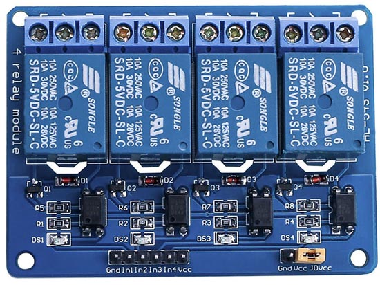
This module contains two channels of the SONGLE relay model SRD-05VDC-SL-C, switching is carried out using a voltage of 5V. Schematically, the module is specially designed to be controlled using low-current boards, such as arduino, raspberry, and so on, which can output a current of not more than 40 mA at the output, and an EL817 optocoupler is added for protection, which implements galvanic isolation. circuit diagram The 2-channel relay module is shown in the figure below.

The dual-channel relay module consists of two independent parts except for the Vcc and GND power supply. When connected to voltage, the In1 output is in a high state (log 1), to switch the first relay, it is necessary to transfer the In1 output to a negative state (log 0), that is, short the circuit to ground. Through the LED, which is located in the optocoupler, current will begin to flow and it will light up, then the phototransistor will open, through which current will also begin to flow to the base of transistor Q1, which will open and the relay will work. The second part of the relay works similarly, the module can also be operated from a separate power source, you need to remove the jumper and connect power to JD-VCC and GND.
Pin assignment
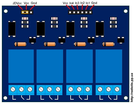
The module contains four connectors, two low-current J1, J1 and two power K1 and K2, the purpose of each connector and output can be seen in the figure below.

The J1 connector is used to control the relay, the pin spacing is 2.54 mm (PLS), the J2 connector is used to connect an external power supply, by default, a jumper is installed between the JD-VCC and VCC contacts.
dimensions
The module has four mounting holes, each 4 mm in diameter, the dimensions can be seen in the figure below.

Required details:
Arduino UNO R3 x 1pc
DuPont wire x 1pc
USB cable 2.0A-B x 1pc
Relay module 2-channel - 5V, 10A, 250V (lOW, OPTO) x 1 pc.
Connection:
First, connect the VCC and GND pins to the Arduino 5V and GND pins. Pins IN1 and IN2 can be connected to any pin, in our case they are connected to digital pins 5 and 6. I use LEDs as an example, the connection diagram is shown in the figure below:

/* Tested on Arduino IDE 1.8 Test date 12/28/2016. */ int in1 = 5; // Specify that the output of the relay In1 is connected to the relay digital output 5 int in2 = 6; // Specify that relay pin In2 is connected to relay digital pin 6 void setup() ( pinMode(in1, OUTPUT); // Set pin 5 as output pinMode(in2, OUTPUT); // Set pin 6 as output ) void loop() ( digitalWrite(in1, HIGH); // Turn off the relay delay(2000); // Wait for 2s digitalWrite(in1, LOW); // Turn on the relay delay(2000); // Wait for 2s digitalWrite(in2, HIGH) ; // Turn off the relay delay(2000); // Wait for 2s digitalWrite(in2, LOW); // Turn on the relay )
Tested on Arduino IDE 1.8 Date of testing 28.12.2016 int in1 = 5 ; // Indicate that the output of the relay In1 is connected to the relay digital output 5 int in2 = 6 ; // We indicate that the output of the relay In2 is connected to the relay digital output 6 void setup() pinMode (in1 , OUTPUT ) ; // Set pin 5 as output pinMode (in2 , OUTPUT ) ; // Set pin 6 as output void loop() digitalWrite(in1 , HIGH ) ; // Turn off the relay delay(2000) ; // Wait 2s digitalWrite (in1 , LOW ) ; // Turn on the relay delay(2000) ; // Wait 2s digitalWrite(in2 , HIGH ) ; // Turn off the relay delay(2000) ; // Wait 2s digitalWrite (in2 , LOW ) ; // Turn on the relay |
![]()

With the help of Arduino. But what if we decide to manage devices connected to the home network? Let me remind you that even a small desk lamp powered by a source alternating current with a voltage of 220 volts. Ordinary field-effect transistor, which we used in the circuit with the engine is no longer suitable. To control a powerful load, and even with alternating current, we use a relay. This is such an electromechanical device that mechanically closes the load circuit using an electromagnet. Let's look at the insides: The principle of operation of the relay is as follows. We apply voltage to the electromagnetic coil. A field appears in the coil, which attracts the metal foot. In turn, the foot mechanically closes the load contacts.  The relay has two main uses. Firstly, we can apply only 5 volts to the coil and close the circuit of a very powerful load. For example, the relay used in the Arduino tutorials can turn on a refrigerator or washing machine. Secondly, some types of relays can simultaneously close and open several different circuits with different voltages at once.
A single relay module has only three contacts. Let's connect them as follows. By the way, the relay input is inverted. This means that the high level on the contact In
will turn the relay coil off, and a low level will turn it on. circuit diagram

Layout appearance

2. Program for Arduino
Let's write a simple program, which will turn on the lamp for 3 seconds and then turn it off for 1 second. const int relPin = 3; void setup() ( pinMode(relPin, OUTPUT); ) void loop() ( digitalWrite(relPin, HIGH); delay(1000); digitalWrite(relPin, LOW); delay(3000); ) Load the Arduino program. Now we connect the power to the lamp and to the relay. Finally, we supply power to the controller.
3. Auto lamp or street lamp
With the help of a controller, a relay and a light sensor, you can make a simple automatic lamp. The controller will turn on the lamp when the light level on the sensor falls below the set value. As a sensor, we use a ready-made module based on . Let's connect all three devices according to the following scheme.circuit diagram

Layout appearance

4. Automatic light program
The analog output of the sensor gives values in the range from 0 to 1023. Moreover, 0 is for the maximum level of light and 1023 for complete darkness. First we need to decide at what level of light to turn on the lamp, and at what turn off. In our laboratory, in daylight, the sensor shows the value L = 120, and at night, about L = 700. We will turn on the relay at L > 600, and turn it off at L< 200. Вспомним как и напишем программу. const int photoPin = A5; const int relPin = 3; void setup() { pinMode(photoPin, INPUT); pinMode(relPin, OUTPUT); } void loop() { if(analogRead(photoPin) < 200) digitalWrite(relPin, HIGH); if(analogRead(photoPin) >600) digitalWrite(relPin, LOW); ) We load the program on Arduino and conduct an experiment. It is best to do this at night.Tasks
1. Music relay. As you know, an electromechanical relay makes a click when triggered. Try using this to play some simple tune. 2. Engine management. With two three-pin relays, like the one in this tutorial, you can build a circuit to change the direction of rotation of the motor./*
*
* ArduinoKit Experiment Kit
* Program code for experiment No. 13: sketch 13
*
* Relay
*
* Written for http://site
*
*
* Help from the Arduino community.
* Visit http://www.arduino.cc
*
*
*
* USING A TRANSISTOR TO CONTROL A RELAY
*
* A relay is an electrically controlled mechanical switch.
* Relay can handle much more voltage and current than ports
* An Arduino, or let's say a transistor, included in the kit. If a
* you want to use Arduino to control incandescent lamp,
* coffee maker, or other electronic device working on 220V,
* Relay is a great way to do this.
* The relay can easily cope with switching, switching, large
* voltages much higher than the Arduino port can offer.
* We will use a transistor to drive a relay,
* just like we used the transistor to drive
* engine in experiment No. 12 (Starter kit, programmer and robotics).
*
* The relay consists of a coil, wire, metal core and
* switching contacts. When power is applied to the coil, the core
* magnetized, and attracts the anchor (lever), thereby
* toggles contacts. Since the relay contacts are completely isolated
* from Arduino, you can safely use the relay to control
* dangerous voltage, BUT! Please do so if you are already
* know and know how to work safely with high voltage!
*
* The relay has three contacts, - COM (common), NC (normally closed)
* and NO (normally open). When the relay is off, COM output
* connected to the NC (normally closed) terminal, and when enabled,
* COM pin is connected to NO (normally open).
*
* This code is very simple - it turns on the relay for one second, then
* turns off, waits a second and turns on again, as in the experiment with a blinking
* LED!
*
* Equipment connection:
*
* Transistor:
* The transistor has three outputs. Looking at the flat side
* pins down, the pin assignments are as follows (left
* on the right): COLLECTOR, BASE, EMITTER.
*
* Connect the BASE through a 1K resistor to digital port 2.
*
* Connect EMITTER to ground (GND).
*
* Relay coil:
*
* The relay has coil contacts that can be used to control
* relays and contacts for load control. on the top or
* the lower part of the relay must have a picture, or a symbol,
* indicating coil contacts.
*
* Connect one side of the coil to the collector of the transistor.
*
* Connect the other side of the coil to a +5 Volt supply.
*
* Diode:
*
* The relay has a coil that you energize in order to
* pull anchor. When the power is turned off, the coil generates
* voltage surge that can damage the transistor. This
* The diode protects the transistor from voltage surge.
*
* Connect the diode lead, CATHODE, to the +5 Volt supply.
*
* Connect the other end of the diode, the ANODE, to the COLLECTOR of the transistor.
*
* Relay and LED contacts:
*
* Relay contacts can switch everything that can be turned on or
* turn off, but we will use relay contacts in this lesson
* to turn the LEDs on and off.
*
* Connect the common output of the relay contact group COMMON to the resistor
* 330 Ohm. The second output of the resistor is +5 volts.
*
* Connect the output of the relay contact group NC (normally closed)
* to positive (long) output LED 1.
*
* Connect the output of the relay contact group NO (normally open)
* to the positive (long) output of the second LED - LED 2.
*
* Connect the negative leads (short legs) of both LEDs
* to ground (GND).
*
*
*
* Comment to the program written
* November 26, 2014
* specially for http: // site
*
*
*/
const int relayPin = 2; // port for transistor control
const int timeDelay = 1000; // delay in ms, between on. and off.
// You can reduce the delay time, but note that
// relay, being mechanical device, will wear out
// faster if switching frequency is too fast.
void setup()
{
pinMode(relayPin, OUTPUT); // set port as outgoing
}
void loop()
{
digitalWrite(relayPin, HIGH); // enable relay
digitalWrite(relayPin, LOW); // turn off the relay
delay(timeDelay); // pause 1 second
Connecting a powerful load directly to the Arduino, such as a lighting lamp or an electric pump, will not work. The microcontroller does not provide the necessary power to operate such a load. The current that can flow through the Arduino outputs does not exceed 10-15 mA. A relay comes to the rescue, with which you can switch a large current. In addition, if the load is powered by alternating current, for example 220v, then you can’t do without a relay at all. To connect powerful loads to the Arduino via relays, relay modules are usually used.
Depending on the number of switched loads, one-, two-, three-, four- and more-channel relay modules are used.
I bought my one and four channel modules on Aliexpress for $ 0.5 and $ 2.09, respectively.
Module relay device for Arduino, using the example of a 4-channel HL-54S V1.0 module.
Let's take a closer look at the device. this module, all multichannel modules are usually built according to this scheme.

Schematic diagram of the module.
To protect the Arduino outputs from voltage surges in the relay coil, a J3Y transistor and an 817C optocoupler are used. Pay attention, the signal from the pin In applied to the cathode of the optocoupler. This means that in order for the relay to close the contacts, you need to apply to the pinIn logical 0 (inverted signal).
There are also modules that have a signal from the pin In applied to the anode of the optocoupler. In this case, you need to submit logic 1 per pinIn, to operate the relay.
The load power that the modules can turn on / off is limited by the relays installed on the board.

In this case, electromechanical relays are used. Songle SRD-05VDC-SL-C, which has the following characteristics:
Operating voltage: 5 V
Coil working current: 71 mA
Maximum switching current: 10A
Maximum switched DC voltage: 28 V
Maximum switched AC voltage
: 250V
Operating temperature:-25 to +70°C
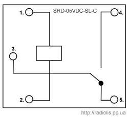
The Songle SRD-05VDC-SL-C relay has 5 pins. 1 and 2 relay power. Contact group 3 and 4 are normally open contacts ( NO), contact group 3 and 5 - normally closed NC).
Similar relays come in various voltages: 3, 5, 6, 9, 12, 24, 48 V. In this case, a 5-volt version is used, which allows you to power the relay module directly from the Arduino.
The board has a jumper ( JDVcc), to power the relay either from the Arduino or from a separate power supply.
Pinami In1,In2,In3,In4 the module is connected to the digital pins of the Arduino.
Connecting the relay module HL-54S V1.0 to Arduino.

Since we have a module with 5-volt relays, we will connect it according to this scheme, we will take power from the Arduino itself. In the example, I will connect one relay, I will use a 220 V light bulb as a load.
To power the relay module from the Arduino, the jumper must close the pins " Vcc" and " JDVcc”, usually by default it is installed there.
If your relay is not 5 volts, you cannot power the module from Arduino, you need to take power from a separate source.
The diagram below shows how to power the module from a separate source. According to this scheme, you need to connect a relay designed to be powered by more or less than 5 V. For 5-volt relays, this scheme will also be more preferable.

With this connection, you need to remove the jumper between the pins " Vcc" and " JDVcc". Next pin " JDVcc» connect to « + » external power supply, pin « Gnd» connect to « - » power supply. Pin " Gnd", which in the previous circuit was connected to the pin" Gnd»Arduino is not connected in this circuit. In my example, the external power supply is 5 V, if your relay is designed for a different voltage (3, 12, 24 V), select the appropriate external power supply.
Sketch for controlling a relay module via Arduino.
Let's upload a sketch to Arduino, which will turn on and off the light bulb (flashing light) itself.
| int relayPin = 7; void setup()( void loop() ( |
In line int relayPin = 7; specify the number of digital pin Arduinoto which the pin was connected In1
module relay. You can connect to any digital pin and specify it in this line.
In line delay(5000); you can change the value of the time at which the light will be on and at which it will be extinguished.
In line digitalWrite(relayPin, LOW); specified, when applying a logical zero ( LOW), the relay module will close the contacts and the light will be on.
In line digitalWrite(relayPin, HIGH); specified, when applying a logical unit ( HIGH), the relay module will open the contacts and the light will go out.
As you can see, in the line digitalWrite(relayPin, LOW); left parameter LOW. If the relay closes the contacts and the light turns on, then the pin In1 you need to feed a logical zero, like me. If the light does not light up, upload the sketch in which we will replace the parameter LOW on the HIGH.
The result of the sketch on the video.
Now let's add a clock button to the circuit and when you click on it, the relay module will turn on the light bulb.

We connect the button together with a 10k pull-up resistor, which will not allow external pickups to affect the operation of the circuit.

Uploading the sketch
In line if(digitalRead(14)==HIGH) set the number of the digital pin on which the button is connected. You can connect to any free. In the example, this analog pinA0, it can also be used as a digital 14 pin.
In line delay(300); the value is given in milliseconds. This value specifies how long after pressing or releasing the button, actions should be performed. This is protection against contact bounce.
For information! All analog inputsfrom A0 ( numbered as 14) to A5 (19), can be used as digital ( digital PWM).
In conclusion, the result of the sketch on the video.
Cheaper relay modules may not contain an optocoupler in their circuit, as, for example, in my case with a single-channel module.
Scheme of a single-channel relay module. The manufacturer saved on an optocoupler, which is why Arduino lost the board galvanic isolation. For the operation of such a board, on pin In must be a logical zero.
Connecting the module relay to the Arduino Due.
The Arduino Due runs on 3.3 volts, which is the maximum voltage it can have on its inputs/outputs. If there will be more high voltage, the board may be burned.
The question arises, how to connect a module to the relay?

Remove the JDVcc jumper. Connect pin " Vcc» on the relay board of the module to pin "3.3V» Arduino. If the relay is rated for 5 volts, connect the pin " GND» module relay board, with pin « GND» Arduino Due. Pin " JDVcc» connect to pin « 5V" on the Arduino board due. If the relay is designed for a different voltage, then we connect the power to the relay as in the figure, in the example it is 5 volts. If you have a multi-channel relay module, please check that « JDVcc » connected to one side of all relays. The optocoupler is activated by a 3.3V signal, which in turn activates the transistor used to turn on the relay.
Triac solid state relay for switching a powerful load via Arduino