FET multivibrator
Novice radio amateurs, of course, know that multivibrators (balanced and unbalanced) perform on bipolar transistors. Unfortunately, such multivibrators have a drawback - when working with a sufficiently powerful load, for example, incandescent lamps, large base currents are required to fully open the transistors.
If the multivibrator arms switch at a frequency of 3 ... 0.2 Hz, it is necessary to install high-capacity oxide capacitors in the frequency-setting circuits, and hence large dimensions. We should not forget about the relatively high saturation voltage of open transistors.
The proposed multivibrator (see figure) uses domestic field-effect n-channel transistors with an insulated gate and an induced channel. Inside the case, between the gate and source terminals, there is a protective zener diode, which significantly reduces the likelihood of a transistor failure if it is handled ineptly.

The switching frequency of the multivibrator transistors is about 2 Hz, it is set by capacitors and resistors. Multivibrator transistor load - incandescent lamps EL1, EL2.
Resistors connected between the drain and the gate of the transistors provide a soft start of the multivibrator. Unfortunately, they "tighten" the switching off of the transistors a little.
Instead of incandescent lamps, it is permissible to include LEDs with 360 Ohm limiting resistors or a telephone capsule, for example, TK-47, into the transistor drain circuit (for this option, the multivibrator must operate in the audio frequency region). In the case of using only one capsule, it is necessary to include a resistor with a resistance of 100 ... 200 Ohm as a load in the drain circuit of another transistor.
Resistors R1, R2 of the ratings indicated in the diagram can be made up of several smaller resistances connected in series. If this option is not available, install smaller resistors and larger capacitors.
Capacitors can be non-polar ceramic or film, for example, series KM-5, KM-6, K73-17. Incandescent lamps are used from a Chinese-made "flashing" Christmas tree garland for a voltage of 6 V and a current of 100 mA. Small-sized lamps for a voltage of 6 V and a current of 60 or 20 mA are also suitable.
Instead of transistors of the specified series, withstanding D.C. up to 180 mA, it is permissible to use keys of the KR1064KT1, KR1014KT1 series designed for a higher current. If you use a multivibrator with a more powerful load, say, car incandescent lamps, you will need other transistors, for example KP744G, which allow a drain current of up to 9 A. But with this option, you need to install protective zener diodes for a voltage of 8 ... 10 V between the gate and the source ( cathode to the gate) - KS191Zh or similar. At high load currents, transistors will have to be installed on heat sinks.
The multivibrator is adjusted by selecting capacitors until the desired switching frequency of the transistors is obtained. To operate the device on audio frequencies capacitors should be 300 ... 600 pF. If you leave the capacitors of the capacitance indicated on the diagram, you will have to select resistors of lower resistance - up to 47 kOhm.
The multivibrator is operational at a supply voltage of 3 ... 10 V, of course, with an appropriate load. If it is supposed to be used as some node in the design being developed, a blocking capacitor with a capacity of 0.1 ... 100 μF is installed between the power wires of the multivibrator.
The multivibrator whose circuit is shown in Figure 1 is a cascade connection transistor amplifiers where the output of the first stage is connected to the input of the second through a circuit containing a capacitor and the output of the second stage is connected to the input of the first through a circuit containing a capacitor. Multivibrator amplifiers are transistor switches that can be in two states. The multivibrator circuit in Figure 1 differs from the trigger circuit discussed in the article "". What has in chains feedback reactive elements so the circuit can generate non-sinusoidal oscillations. You can find the resistance of resistors R1 and R4 from relations 1 and 2:
Where I KBO \u003d 0.5 μA is the maximum reverse current of the collector of the transistor kt315a,
Ikmax=0.1A - maximum collector current of the kt315a transistor, Up=3V - supply voltage. Let's choose R1=R4=100Ω. Capacitors C1 and C2 are selected depending on the desired frequency of the multivibrator.
Figure 1 - Multivibrator on KT315A transistors
You can remove the voltage between points 2 and 3 or between points 2 and 1. The graphs below show how the voltage will approximately change between points 2 and 3 and between points 2 and 1.
T - oscillation period, t1 - time constant of the left arm of the multivibrator, t2 - time constant of the right arm of the multivibrator can be calculated by the formulas:
You can set the frequency and duty cycle of the pulses generated by the multivibrator by changing the resistance of the tuning resistors R2 and R3. You can also replace the capacitors C1 and C2 with variables (or trimmers) and by changing their capacitance set the frequency and duty cycle of the pulses generated by the multivibrator, this method is even more preferable, so if there are trimmer (or better variable) capacitors, it is better to use them, but in place variable resistors R2 and R3 set constant. The photo below shows the assembled multivibrator:
In order to make sure that the assembled multivibrator works, a piezo speaker was connected to it (between points 2 and 3). After applying power to the circuit, the piezo speaker began to crack. Changes in the resistance of the tuning resistors led either to an increase in the frequency of the sound emitted by the piezo speaker or to its decrease, or to the fact that the multivibrator stopped generating.
The program for calculating the frequency, period and time constants, duty cycle of pulses taken from the multivibrator:
If the program does not work, then copy it html code into notepad and save as html.
If used Internet browser Explorier and it blocks the program, you must allow the blocked content.
js is disabled
Other multivibrators:
In this article we will talk about the multivibrator, how it works, how to connect the load to the multivibrator and calculate the transistor symmetrical multivibrator.
multivibrator is a simple generator rectangular pulses, which works in autogenerator mode. It only needs battery power or other power source to operate. Consider the simplest symmetrical transistor multivibrator. Its scheme is shown in the figure. The multivibrator can be complicated depending on the required functions to be performed, but all the elements shown in the figure are mandatory, without them the multivibrator will not work.
The operation of a symmetrical multivibrator is based on the charge-discharge processes of capacitors, which together with resistors form RC chains.
I wrote about how RC chains work earlier in my article Capacitor, which you can read on my website. On the Internet, if you find material about a symmetrical multivibrator, then it is presented briefly and not intelligibly. This circumstance does not allow novice radio amateurs to understand anything, but only helps experienced electronic engineers to remember something. At the request of one of the visitors to my site, I decided to eliminate this gap.
How does a multivibrator work?

At the initial moment of power supply, the capacitors C1 and C2 are discharged, so their current resistance is small. The low resistance of the capacitors leads to the fact that there is a "fast" opening of the transistors, caused by the flow of current:
- VT2 along the way (shown in red): "+ power supply> resistor R1> low resistance of discharged C1> base-emitter junction VT2> - power supply";
- VT1 along the way (shown in blue): "+ power supply> resistor R4> low resistance of discharged C2> base-emitter junction VT1> - power supply".
This is the "unsteady" mode of operation of the multivibrator. It lasts for a very short time, determined only by the speed of the transistors. And two absolutely identical transistors do not exist. Which transistor opens faster, that one will remain open - the "winner". Suppose that in our diagram it turned out to be VT2. Then, through the low resistance of the discharged capacitor C2 and the low resistance of the collector-emitter junction VT2, the base of the transistor VT1 will be closed to the emitter VT1. As a result, the transistor VT1 will be forced to close - "become defeated."

Since the transistor VT1 is closed, there is a “fast” charge of the capacitor C1 along the path: “+ power source> resistor R1> low resistance of the discharged C1> base-emitter junction VT2> - power source”. This charge occurs almost up to the voltage of the power supply.
At the same time, the capacitor C2 is charged with a current of reverse polarity along the path: “+ power source> resistor R3> low resistance of the discharged C2> collector-emitter junction VT2> - power source”. The duration of the charge is determined by the values of R3 and C2. They determine the time at which VT1 is in the closed state.

When the capacitor C2 is charged to a voltage approximately equal to a voltage of 0.7-1.0 volts, its resistance will increase and the transistor VT1 will open with a voltage applied along the path: “+ power supply> resistor R3> base-emitter junction VT1> - power source". In this case, the voltage of the charged capacitor C1, through the open collector-emitter junction VT1, will be applied to the emitter-base junction of the transistor VT2 with reverse polarity. As a result, VT2 will close, and the current that previously passed through the open collector-emitter junction VT2 will run through the circuit: “+ power supply> resistor R4> low resistance C2> base-emitter junction VT1> - power source”. This circuit will quickly recharge the capacitor C2. From this moment, the "steady" mode of autogeneration begins.
The operation of a symmetrical multivibrator in the "steady" generation mode
The first half-cycle of operation (oscillation) of the multivibrator begins.

With the transistor VT1 open and VT2 closed, as I just wrote, capacitor C2 is quickly recharged (from a voltage of 0.7 ... 1.0 volts of one polarity to the power supply voltage of the opposite polarity) along the circuit: “+ power supply> resistor R4 > low resistance C2 > base-emitter junction VT1 > - power supply. In addition, the capacitor C1 is slowly recharged (from the voltage of the power supply of one polarity to a voltage of 0.7 ... 1.0 volts of the opposite polarity) along the circuit: “+ power supply> resistor R2> right plate C1> left plate C1> collector- emitter junction of the transistor VT1> - power supply".
When, as a result of overcharging C1, the voltage at the base of VT2 reaches a value of +0.6 volts relative to the emitter of VT2, the transistor will open. Therefore, the voltage of the charged capacitor C2, through the open collector-emitter junction VT2, will be applied to the emitter-base junction of the transistor VT1 with reverse polarity. VT1 will close.
The second half-cycle of operation (oscillation) of the multivibrator begins.

When the transistor VT2 is open and VT1 is closed, the capacitor C1 is quickly recharged (from a voltage of 0.7 ... 1.0 volts of one polarity to the power supply voltage of the opposite polarity) along the circuit: “+ power supply> resistor R1> low resistance C1> base- emitter junction VT2 > - power supply". In addition, there is a slow recharge of the capacitor C2 (from the voltage of the power supply of one polarity, to a voltage of 0.7 ... 1.0 volts of the opposite polarity) along the circuit: “right plate C2> collector-emitter junction of the transistor VT2> - power supply> + source power > resistor R3 > left plate C2. When the voltage at the base of VT1 reaches +0.6 volts relative to the emitter of VT1, the transistor will open. Therefore, the voltage of the charged capacitor C1, through the open collector-emitter junction VT1, will be applied to the emitter-base junction of the transistor VT2 with reverse polarity. VT2 will close. On this, the second half-cycle of the multivibrator oscillation ends, and the first half-cycle begins again.
The process is repeated until the multivibrator is disconnected from the power source.
Ways to connect the load to a symmetrical multivibrator

Rectangular pulses are taken from two points of a symmetrical multivibrator- collectors of transistors. When there is a “high” potential on one collector, then there is a “low” potential on the other collector (it is absent), and vice versa - when there is a “low” potential on one output, then “high” on the other. This is clearly shown in the timeline below.
The multivibrator load must be connected in parallel with one of the collector resistors, but in no case in parallel with the collector-emitter transistor junction. You can not shunt the transistor with a load. If this condition is not met, then at least the duration of the pulses will change, and as a maximum, the multivibrator will not work. The figure below shows how to connect the load correctly, and how not to do it.

In order for the load not to affect the multivibrator itself, it must have sufficient input impedance. For this, buffer transistor stages are usually used.
The example shows connecting a low-resistance dynamic head to a multivibrator. An additional resistor increases the input resistance of the buffer stage, and thereby eliminates the influence of the buffer stage on the multivibrator transistor. Its value must be at least 10 times the value of the collector resistor. Connecting two transistors in a "composite transistor" scheme greatly increases the output current. In this case, it is correct to connect the base-emitter circuit of the buffer stage in parallel with the collector resistor of the multivibrator, and not in parallel with the collector-emitter junction of the multivibrator transistor.
For connecting a high-impedance dynamic head to a multivibrator buffer stage is not needed. The head is connected instead of one of the collector resistors. The only condition that must be met is that the current flowing through the dynamic head must not exceed the maximum collector current of the transistor.
If you want to connect ordinary LEDs to the multivibrator- to make a flasher, then buffer cascades are not required for this. They can be connected in series with collector resistors. This is due to the fact that the current of the LED is small, and the voltage drop across it during operation is not more than one volt. Therefore, they do not have any effect on the operation of the multivibrator. True, this does not apply to super-bright LEDs, in which the operating current is higher and the voltage drop can be from 3.5 to 10 volts. But in this case, there is a way out - to increase the supply voltage and use transistors with high power, providing sufficient collector current.
Please note that oxide (electrolytic) capacitors are connected with pluses to the collectors of transistors. This is due to the fact that on the bases of bipolar transistors, the voltage does not rise above 0.7 volts relative to the emitter, and in our case, emitters are a minus of power. But on the collectors of transistors, the voltage changes almost from zero to the voltage of the power source. Oxide capacitors are not able to perform their function when they are connected with reverse polarity. Naturally, if you use transistors of a different structure (not N-P-N, a P-N-P structures), then in addition to changing the polarity of the power source, it is necessary to turn the LEDs with cathodes "up the circuit", and the capacitors - pluses to the bases of the transistors.
Let's figure it out now what parameters of the multivibrator elements set the output currents and generation frequency of the multivibrator?
What are the collector resistor values? I have seen in some incompetent Internet articles that the values of the collector resistors are insignificant, but they affect the frequency of the multivibrator. All this is complete nonsense! With the correct calculation of the multivibrator, the deviation of the values \u200b\u200bof these resistors by more than five times from the calculated one will not change the frequency of the multivibrator. The main thing is that their resistance should be less than the base resistors, because the collector resistors provide a fast charge of the capacitors. But on the other hand, the values of the collector resistors are the main ones for calculating the power consumption from the power source, the value of which should not exceed the power of the transistors. If you figure it out, then correct connection they do not even directly affect the output power of the multivibrator. But the duration between switching (multivibrator frequency) is determined by the "slow" recharge of the capacitors. The recharge time is determined by the values of RC chains - basic resistors and capacitors (R2C1 and R3C2).

The multivibrator, although it is called symmetrical, refers only to the circuitry of its construction, and it can produce both symmetrical and non-symmetrical output pulses. The duration of the pulse (high level) on the VT1 collector is determined by the values of R3 and C2, and the duration of the pulse (high level) on the VT2 collector is determined by the values of R2 and C1.
The duration of the recharge of capacitors is determined by a simple formula, where Tau is the pulse duration in seconds, R is the resistance of the resistor in ohms, FROM is the capacitance of the capacitor in Farads:
Thus, if you have not already forgotten what was written in this article a couple of paragraphs earlier:
If equal R2=R3 and C1=C2, at the outputs of the multivibrator there will be a “meander” - rectangular pulses with a duration equal to the pauses between the pulses, which you see in the figure.
The total period of oscillation of the multivibrator is T is equal to the sum of the pulse and pause durations:
![]()
Oscillation frequency F(Hz) related to period T(sec) through the ratio:
As a rule, if there are any calculations of radio circuits on the Internet, they are scarce. That's why we will calculate the elements of a symmetrical multivibrator using an example .
Like any transistor cascades, the calculation must be carried out from the end - the output. And at the output we have a buffer stage, then there are collector resistors. Collector resistors R1 and R4 perform the function of loading transistors. Collector resistors have no effect on the generation frequency. They are calculated based on the parameters of the selected transistors. Thus, we first calculate the collector resistors, then the base resistors, then the capacitors, and then the buffer stage.
The order and example of calculating a transistor symmetrical multivibrator
Initial data:
Supply voltage Ui.p. = 12 V.
Required multivibrator frequency F = 0.2 Hz (T = 5 seconds), and the pulse duration is equal to 1 (one) second.
An incandescent car light bulb is used as a load. 12 volts, 15 watts.
As you guessed, we will calculate the flasher, which will flash once every five seconds, and the duration of the glow will be 1 second.
Choosing transistors for the multivibrator. For example, we have the most common transistors in Soviet times KT315G.
For them: Pmax=150 mW; Imax=150 mA; h21>50.
Transistors for the buffer stage are selected based on the load current.
In order not to depict the circuit twice, I have already signed the values of the elements on the diagram. Their calculation is given later in the Decision.

Solution:
1. First of all, it is necessary to understand that the operation of a transistor at high currents in the key mode is the safest for the transistor itself than operation in the amplifying mode. Therefore, there is no need to calculate the power for the transition state at the moments of the passage of an alternating signal, through the operating point "B" of the static mode of the transistor - the transition from the open state to the closed state and vice versa. For pulse circuits, built on bipolar transistors, usually calculate the power for transistors that are in the open state.
First, we determine the maximum power dissipation of the transistors, which should be a value that is 20 percent less (a factor of 0.8) than the maximum power of the transistor indicated in the reference book. But why should we drive the multivibrator into a rigid frame of high currents? Yes, and from increased power, energy consumption from the power source will be large, but there will be little benefit. Therefore, having determined the maximum power dissipation of transistors, we will reduce it by 3 times. A further reduction in dissipated power is undesirable because the operation of a multivibrator on bipolar transistors in the low current mode is an “unstable” phenomenon. If the power supply is used not only for the multivibrator, or it is not quite stable, the frequency of the multivibrator will also “float”.
Determine the maximum power dissipation: Pras.max = 0.8 * Pmax = 0.8 * 150mW = 120mW
We determine the rated power dissipation: Pras.nom. = 120 / 3 = 40mW
2. Determine the collector current in the open state: Ik0 = Pras.nom. / Ui.p. = 40mW / 12V = 3.3mA
Let's take it as the maximum collector current.
3. Find the value of the resistance and power of the collector load: Rk.total = Ui.p. / Ik0 = 12V / 3.3mA = 3.6 kOhm
We select resistors as close as possible to 3.6 kOhm in the existing nominal range. In the nominal series of resistors there is a nominal value of 3.6 kOhm, therefore, we first consider the value of the collector resistors R1 and R4 of the multivibrator: Rk \u003d R1 \u003d R4 \u003d 3.6 kOhm.
The power of the collector resistors R1 and R4 is equal to the rated power dissipation of the transistors Pras.nom. = 40 mW. We use resistors with a power exceeding the specified Pras.nom. - MLT-0.125 type.
4. Let's proceed to the calculation of the basic resistors R2 and R3. Their value is found based on the gain of the transistors h21. At the same time, for reliable operation of the multivibrator, the resistance value must be within: 5 times the resistance of the collector resistors, and less than the product Rk * h21. In our case Rmin \u003d 3.6 * 5 \u003d 18 kOhm, and Rmax \u003d 3.6 * 50 \u003d 180 kOhm
Thus, the resistance values Rb (R2 and R3) can be in the range of 18...180 kOhm. We pre-select the average value = 100 kOhm. But it is not final, since we need to provide the required frequency of the multivibrator, and as I wrote earlier, the frequency of the multivibrator directly depends on the base resistors R2 and R3, as well as on the capacitance of the capacitors.
5. Calculate the capacitances of capacitors C1 and C2 and, if necessary, recalculate the values of R2 and R3.
The values of the capacitance of the capacitor C1 and the resistance of the resistor R2 determine the duration of the output pulse on the collector VT2. It is during the action of this pulse that our light bulb should light up. And in the condition, the pulse duration was set to 1 second.
determine the capacitance of the capacitor: C1 \u003d 1 sec / 100kOhm \u003d 10 uF
A capacitor with a capacity of 10 microfarads is available in the nominal range, so it suits us.
The values of the capacitance of the capacitor C2 and the resistance of the resistor R3 determine the duration of the output pulse on the collector VT1. It is during the action of this pulse that a “pause” operates on the VT2 collector and our light should not light up. And in the condition, a full period of 5 seconds was set with a pulse duration of 1 second. Therefore, the duration of the pause is 5 seconds - 1 second = 4 seconds.
By transforming the recharge duration formula, we determine the capacitance of the capacitor: C2 \u003d 4sec / 100kOhm \u003d 40 uF
A 40 uF capacitor is not in the nominal series, so it does not suit us, and we will take a 47 uF capacitor as close as possible to it. But as you understand, the “pause” time will also change. To prevent this from happening, we recalculate the resistance of the resistor R3 based on the duration of the pause and the capacitance of the capacitor C2: R3 = 4sec / 47uF = 85kΩ
According to the nominal series, the nearest value of the resistance of the resistor is 82 kOhm.
So, we got the values of the elements of the multivibrator:
R1 = 3.6 kΩ, R2 = 100 kΩ, R3 = 82 kΩ, R4 = 3.6 kΩ, C1 = 10 uF, C2 = 47 uF.
6. Calculate the value of the resistor R5 of the buffer stage.
The resistance of the additional limiting resistor R5 to eliminate the effect on the multivibrator is selected at least 2 times the resistance of the collector resistor R4 (and in some cases more). Its resistance, together with the resistance of the emitter-base junctions VT3 and VT4, in this case will not affect the parameters of the multivibrator.
R5 = R4 * 2 = 3.6 * 2 = 7.2 kΩ
According to the nominal series, the nearest resistor is 7.5 kOhm.
With the value of the resistor R5 = 7.5 kOhm, the buffer stage control current will be equal to:
I ex. \u003d (Ui.p. - Ube) / R5 \u003d (12v - 1.2v) / 7.5 kOhm \u003d 1.44 mA
In addition, as I wrote earlier, the value of the collector load of the multivibrator transistors does not affect its frequency, so if you do not have such a resistor, then you can replace it with another "close" value (5 ... 9 kOhm). It is better if this is in the direction of decreasing, so that there is no drop in the control current at the buffer stage. But keep in mind that the additional resistor is an additional load on the VT2 transistor of the multivibrator, so the current flowing through this resistor adds up to the current of the collector resistor R4 and is a load for the VT2 transistor: Itotal \u003d Ik + Iupr. = 3.3mA + 1.44mA = 4.74mA
The total load on the collector of the transistor VT2 is within normal limits. If it exceeds the maximum collector current specified in the reference book and multiplied by a factor of 0.8, increase the resistance R4 until the load current is sufficiently reduced, or use a more powerful transistor.
7. We need to provide current to the light bulb In \u003d Rn / Ui.p. = 15W / 12V = 1.25 A
But the buffer stage control current is 1.44mA. The multivibrator current must be increased by a value equal to the ratio:
In / I ex. = 1.25A / 0.00144A = 870 times.
How to do it? For a significant increase in output current use transistor cascades built according to the "composite transistor" scheme. The first transistor is usually low-power (we will use KT361G), it has the highest gain, and the second must provide sufficient load current (take the no less common KT814B). Then their gains h21 are multiplied. So, for the transistor KT361G h21> 50, and for the transistor KT814B h21=40. And the overall transfer coefficient of these transistors, connected according to the "composite transistor" scheme: h21 = 50 * 40 = 2000. This figure is more than 870, so these transistors are enough to drive a light bulb.
Well, that's all!
Symmetrical and single-ended multivibrators for various purposes can be built not only on bipolar transistors, but also on field ones. One example of this can be found in . Considering that field-effect transistors have a number of advantages over bipolar ones, the main of which is the extremely low current in the control circuit when operating at a low frequency or in a static mode, it can be assumed that a conventional two-transistor multivibrator, but only on field effect transistors, will be in a winning position over similar nodes assembled on their bipolar counterparts.
You can see the scheme of the first mulvibrator in fig. 1. Its operation is in many ways similar to the operation of a multivibrator on pnp bipolar transistors - the LEDs will also wink. The difference is that to close each of the transistors VT1.1, VT1.2, it is necessary to apply a positive gate-source voltage, which must exceed the cut-off voltage of these transistors (about 4 V). This happens every time the multivibrator arms are switched, due to the presence of time-setting capacitors C1, C2. That is why there is no need for a bipolar power supply.

The switching frequency of transistors in this generator is once every 6 s. When installing high-quality electrolytic capacitors (with a low leakage current), with a capacity of 100 ... 4700 μF, it is possible to achieve transistor switching with a period of several tens of minutes, which is unattainable for simple devices on bipolar transistors.
The resistances of resistors R2 and R3 can differ by several thousand times, for example, R2 can be taken as 30 MΩ, and R3 as 10 kΩ. The multivibrator will then become asymmetrical. The capacitances of the capacitors change in the same way. Having properly selected these elements, it is possible to obtain very short pulses at the drain output of one of the transistors, following with a large duty cycle (100 ... 10000). If in a device made according to the scheme of Fig. 1, instead of ordinary LEDs, turn on blinking transistors as a load of transistors, for example, L-36BSRD, then any of them, blinking several times, will rest while its neighbor blinks. If you need to operate the multivibrator at audio frequencies, then the resistance of resistors R2 and R3 reduce by 10 ... 20 times, and take capacitors with a capacity of several hundred picofarads.
Instead of conventional resistors R2, R3, you can install photoresistors (FSK, SF2-x, SFZ-x, FR117, etc.). In this case, the switching frequency of transistors will change several thousand times depending on the level of illumination. It should only be noted that if the resistance of the resistors R2, R3 is less than 3 kΩ, the generation may fail.
A multivibrator made according to the scheme shown in fig. 1, requires the use of field-effect transistors with a large initial drain current (10 ... 30 mA). In the absence of such assemblies from the KR504 series, it is possible to assemble a similar multivibrator according to the scheme shown in Fig. 2. Here, field-effect transistors operate with a lower drain current, and in order to obtain sufficient brightness of the LEDs, current amplifiers are installed on bipolar transistors VT1, VT4. The switching frequency of this multivibrator is about 1 Hz. If you install powerful composite transistors from the KT829 series in place of transistors VT1, VT4, then incandescent lamps can be used as their load. In this case, R2, R6 are not installed, since transistors of the KT829 type contain their own built-in resistors.
If this multivibrator "refuses" to work, then resistors R3, R7 should be more accurately selected. In a node assembled according to the scheme shown in Fig. 1, it is possible to use microassemblies of matched pairs of field-effect transistors of the KR504, (K504, 504) series with an initial drain current of more than 10 mA. KR504NT4V, KR504NTZV are most suitable, but you can try with indexes A, B. When changing the polarity of the supply voltage and connecting LEDs, instead of a transistor assembly, you can use two separate field-effect n-channel transistors from the KP302, KP307 series. If they have a large cutoff voltage, then the supply voltage can be increased to 15 V.

For the node, the scheme of which is shown in Fig. 2, KR504NT1, KR504NT2 microcircuits with any letter index are suitable, and when selecting resistors R3, R7 - KR504NTZ, KR504NT4. In addition, many field-effect transistors of the KP103, KP101 series will also work without tuning. It is better to use non-polar capacitors, for example, small-sized K73-17 for 63 V. "Regular" LEDs can be any of the AL307, KIPD21, KIPD35, KIPD40 series, as well as 1-1513, L-934, etc. Flashing - L-816BRSC-B, L-769BGR, L-56DGD, Т1ВК5410 and others.
Since the field-effect transistors of the KR504NT (1 ... 4) assemblies allow a maximum source-drain voltage of not more than 10 V, the supply voltage of the multivibrators should not exceed 10 ... 12 V.
Literature
Publication: www.cxem.net
The operation of the multivibrator circuit
Symmetrical multivibrator on transistors
Schematically, the multivibrator consists of two amplifying stages with a common emitter, output voltage each of which is fed to the input of the other. When the circuit is connected to a power source Ek, both transistors pass collector points - their operating points are in the active region, since a negative bias is applied to the bases through resistors RB1 and RB2. However, this state of the circuit is unstable. Due to the presence of positive feedback in the circuit, the condition?Ku>1 is satisfied and the two-stage amplifier is self-excited. The regeneration process starts rapid increase current of one transistor and a decrease in current of the other transistor. Let the current IK1 of the transistor VT1 increase slightly as a result of any random change in the voltages on the bases or collectors. This will increase the voltage drop across the resistor RK1 and the collector of the transistor VT1 will receive an increment of positive potential. Since the voltage on the capacitor SB1 cannot change instantly, this increment is applied to the base of the transistor VT2, blocking it. At the same time, the collector current IK2 decreases, the voltage on the collector of the transistor VT2 becomes more negative and, passing through the capacitor SB2 to the base of the transistor VT1, opens it even more, increasing the current IK1. This process proceeds like an avalanche and ends with the fact that the transistor VT1 enters the saturation mode, and the transistor VT2 enters the cutoff mode. The circuit enters one of its temporarily stable equilibrium states. In this case, the open state of the transistor VT1 is provided by a bias from the power source Ek through the resistor RB1, and the locked state of the transistor VT2 is ensured by a positive voltage on the capacitor SB1 (Ucm = UB2 > 0), which is connected through the open transistor VT1 to the base-emitter interval of the transistor VT2.
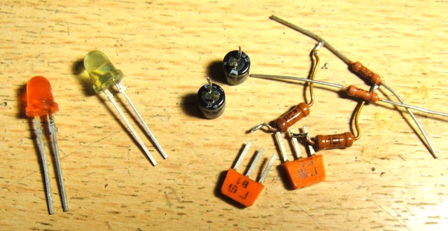
For the construction of a multivibrator from the radio components we need:1. Two transistors of the KT315 type.
2. Two electrolytic capacitors for 16V, 10-200 microfarads (The smaller the capacitance, the more blinking).
3. 4 resistors with a nominal value: 100-500 ohms 2 pieces (if you set 100 ohms, then the circuit will work even from 2.5v), 10 kOhm 2 pieces. All resistors are 0.125 watts.
4. Two non-bright LEDs (Any color other than white).

Printed circuit board in Lay6 format. Let's start manufacturing. Herself printed circuit board looks like this:
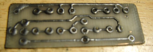
We solder two transistors, do not confuse the collector and base on the transistor - this is a common mistake.
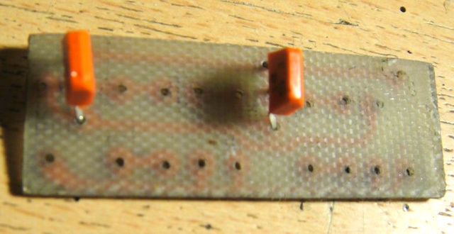
We solder capacitors 10-200 microfarads. Note that 10 volt capacitors are highly undesirable for this circuit if you are supplying 12 volts. Remember that electrolytic capacitors have polarity!

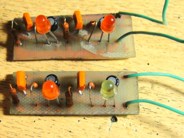
The multivibrator is almost ready. It remains to solder the LEDs, and the input wires. A photo of the finished device looks something like this:
And so that everything becomes clear to you, a video of the operation of a simple multivibrator:
In practice, multivibrators are used as pulse generators, frequency dividers, pulse shapers, contactless switches, and so on, in electronic toys, automation devices, computing and measuring equipment, in time relays and setting devices. was with you Boil-:D . (material was prepared on request Demyan" a)
Discuss the article MULTIVIBRATOR