Many people think passing by the market rows with Chinese products. Clocks that run for a month, kettles that boil for a week, hair dryers that blow for two hours.
All this is so. Nearly. But not really.
So, in order:
FIRST INSIDE IMPRESSION:
Cover fasteners, as a rule, with latches, plus a few screws, but if there are 4 or more screws, then there are no latches. For small cases, sometimes screws are not provided at all, sometimes there are 1 ... 2 pcs. Before opening the case, look carefully for these screws (for example, in the power compartment). They need to be unscrewed. Sometimes there is another screw opposite telescopic antenna. He fastens it. This screw does not need to be removed.
The installation is such that the front and rear end connected by wires. For operation, it doesn’t matter, but for tuning and repair, it’s a nasty little thing. In addition, the wires themselves are very economical. A plastic insulator of normal thickness (as MGShV 0.16 ... 0.25), and inside there are 3 ... 4 of the thinnest copper veins. When repairing these wires, they crumble like dust. They are usually soldered not where the Chinese designer came up with, but where the Chinese worker wanted. The designer cared about the nobility of the design, and the worker wanted to make fewer movements. As a result, the wires are not connected to specially dedicated printed pads, but nearby (it is already tinned there) or even to the other side of the board (it is really more convenient there). But during operation, all this has no role and does not play any significance. The second characteristic Chinese flaw is the randomly lying parts. Of course, the crooked part works fine, but the view is disgusting. The same conflict between the designer and the worker is to blame for everything. And the designer is 95% to blame here. Yet, although he is not a scoop, he lives in a socialist country. I think this is the reason. Good constructor(the designer) will lay down in advance what the worker will do. Since electrolytic capacitors are lying around, it is necessary to immediately develop a board with parts laid on its side. I will also mention that printed circuit boards on getinaks (this is almost always in consumer goods), but the quality of both getinaks and boards is quite decent.
The speaker (dynamic direct-radiation head) with a nice shiny cap, but that's probably all that can be said about it. Sometimes (not often) fails due to a broken voice coil).
The KPI (Variable Capacitor - Provides frequency tuning) is perhaps the best part of these receivers. Four-section (two sections AM and two - VHF) with four trimmers. In general, a dream. Sometimes wax gets inside, which fixes the coils and then the KPI comes to an end.
The vernier is most often made as a plastic strip connected to the KPI tuning disk. Sometimes it is firmly attached to the KPI disk (it comes off if the receiver is roughly disassembled and glued back is difficult), sometimes it is separated along with a small plastic insert, sometimes it is a toothed strip (it works very reliably), but you have to tinker with the precise installation of the gear on the desired tooth, and sometimes a classic thread (this case is the angrier of all: if something breaks, you can fix it).
Range switches are not bad, but also suffer from wax.
The potentiometer (volume control) and the same power switch, in my opinion, are rather frail by Russian standards. It can be twisted, loosened. Almost half of the defects are related to this part. The frail textolite cam of the switch also breaks, and the resistor itself can crack and the wheel fall off. Worse than this potentiometer are only potentiometers from Russia, although they are made according to the same Russian standards.
Resistors. Circuitry is such that there are almost none. And it is right. In practice, resistors appear only in different versions of ULF and volume control circuits.
Crystal IF filters: 10.7 MHz for VHF and 455 kHz for AM bands. Filters are common for modern equipment.
Screws, screws and self-tapping screws. There are not many of them and this is good, since they need to be screwed and tightly. As a rule, the case is screwed qualitatively. The remaining screws can dangle and unscrew (one of the characteristic defects is that the volume control wheel is poorly screwed.
Plastic. A good plastic molding in China. I like. The plastic is durable, hard, with a good texture. Sometimes the cases are made of painted plastic (the color is beautiful, mother-of-pearl, with a spark...). It's better not to take these. Very soon, the paint will begin to peel off and the appearance of the device will be the same. At elevated temperatures, thin plastic on the scale (both above and below the scale) behaves poorly. You might think there is no sun in China. Even in our latitudes, the scales are warped under the May sun like in a frying pan.
Setting. Let's just say none. It’s good that you don’t need to adjust the UPCH (piezo filters are everywhere). But where it is necessary to adjust, it is done poorly there. If the receiver does not catch well, then poor tuning is to blame in 90% of cases. The input circuit and the frequency discriminator circuit are two tuning kits. How to set up (or rebuild) .
A large receiver sometimes has a larger speaker. That's the whole difference between different models. Of course, in a large case, even a small speaker sounds better.
FIRST, EXTERNAL, IMPRESSION: a huge variety, but if the store has 100 varieties of cheese, then why not have 100 varieties of receivers. Appearance is cute, maybe a little Chinese voluptuous. How they love small decorations, roses, flowers. But we are already used to it, and not all models are like that. If we compare external design receivers of the CIS and China, then there is nothing to talk about. A primitive appearance, uncomfortable regulators, some kind of ugly-looking plastic - all these are the prerogatives of Russian consumer goods.
COMPONENTS: almost all Korean or Japanese. Everything is close by and apparently very inexpensive.
Capacitors are ceramic and electrolytic. It would be better if they were smaller. The circuit is pretty clogged with electrolytic capacitors. There are more of them only in Russian receivers.
The contours are more or less unified and it pleases. For everything about everything, there are heels of the most popular coils wound on ferrite spools and placed in a ferrite cup that can be screwed up for tuning. There are three standard sizes of contours: small, even smaller and the smallest. The contours would be completely beyond criticism if it were not for the frail legs, which, when soldering, strive to start an independent life.
Transistors. The most common. In case of repair, they are replaced by KT3102 or KT3107 (depending on the type of conductivity).
Microcircuits. Korean or Japanese. Usually this is TA2003 (not to be confused with TDA2003) from TOCHIBA or CXA1191 (SONY) or its equivalent - KA22425 (SAMSUNG). The first of these three types of microcircuits does not contain ULF and receivers with this microcircuit shine with a variety of amplifiers from a transformer push-pull circuit to integrated ULF different types. The CXA chip has an increased input sensitivity, especially on VHF, but often its input amplifier fails and then the receiver catches almost nothing at all; KA chip - has very uneven characteristics from copy to copy. Sometimes it catches great, sometimes so-so, and sometimes not at all. There is a suspicion that the cunning Chinese are buying rejected microcircuits at a low price. You can avoid trouble when buying by choosing the right receiver from several. (See below for how to choose.)
General circuitry has two options, since there are also two types of microcircuits. TA2003, in my opinion, catches and sounds a little worse, since it requires good ULF tuning (but tuning in China is as always tight), and this microcircuit was developed earlier than CXA1191 (late development is always better). The scheme is almost the same as recommended by the chip designer. The only difference is the replacement of the 10.7 MHz quartz in the frequency detector with a circuit with the same frequency. I don’t know what’s the matter, but I haven’t seen this quartz in any of the many hundreds of receivers (the developer recommends a quartz resonator (discriminator) of the CDA 10.7MG31 MURATA MFG.CO., LTD type).
General systems engineering., or rather its complete and brilliant absence. A dozen firms produce hundreds of models, and each model (may have several variants) is made as if there were no other receivers in nature. Except outright blunders it is not clear why, for example, some receivers have a mono jack for headphones (headphones), while ordinary stereo phones have only one ear. The power socket (if there is: it seems difficult to put it everywhere) sometimes has + on the external contact (more often, although this is complete game), and sometimes on the internal one. Sometimes a small jack is used for power, sometimes a 3.5mm jack, and sometimes a 5.5mm jack. The most interesting thing is that even for one company, the larger the size of the receiver, the larger the size of the printed circuit board, although their circuits are absolutely identical. And on large boards there seems to be no empty space, and on small boards it is not very crowded. This riddle needs to be thought through. In all (almost) models, the power circuit is not fully developed. If you have an inexhaustible source of batteries, then everything is in order, but if you lead an economical lifestyle, then it would be better to use batteries. There is something to think about.
DEFECTS AND FAULTS
HOW TO CHOOSE:
Intermediate frequencies of radio receivers:
 You need to enable Javascript!
450 kHz- the standard of imported, most often Chinese, radios
455 kHz- the main standard of imported radios
465 kHz- Soviet intermediate frequency standard
500 kHz- used in receivers with electromechanical filters (EMF)
For those who forgot...
As a rule, modern mass models of radio receivers are made according to a superheterodyne scheme with one frequency conversion. Let's remember how it works.For a better understanding, you should know that most of the circuitry of such receivers is "good old" direct gain receiver!
This is an amplifier tuned to a constant radio frequency (455, 465 or 500 kHz), a detector, an audio frequency amplifier (previously said " low frequency amplifier"), system automatic adjustment gain (AGC). All these are elements of the circuit of a direct amplification receiver.
Advantages and disadvantages of superheterodyne
Loops tuned to a constant frequency (455, 465, or 500 kHz) provide good adjacent channel bandwidth. That is, the neighboring station is weakened and does not interfere with reception. And the circuits themselves are tuned once at the factory with coil cores with constant capacitors. An amplifier with such a relatively low frequency is more resistant to self-excitation and provides good gain. But! The trouble is that few people will be interested in receiving one frequency ... :-)
Therefore, a low-power, frequency-tunable, high-frequency generator (the so-called " heterodyne") and a mixer that mixes:
a) a signal from the local oscillator and
b) signals from the antenna.
Sometimes the local oscillator and the mixer are made with just one radio tube or one transistor.
What is important for us is that as a result of mixing signals, a signal difference is obtained. And when this difference is, say, 465 kHz, the signal is further processed by the direct amplification receiver.
Note that such receivers are called " superheterodyne"with one frequency conversion. A constant, let's call it auxiliary, the frequency of 455, 465 or 500 kHz has a common name -" intermediate frequency (IF)". Which intensifies intermediate frequency amplifier (IFA). In the simplest version, the UFC is also done on a single radio tube or transistor.
For example, the IF at the receiver is 500 kHz. And we want to receive a station on 1000 kHz. The local oscillator usually operates higher in frequency. So the local oscillator should work at 1000 + 500 = 1500 kHz. For it is with this setting of the local oscillator that we get an IF difference of 500 kHz.
But, (attention!) We will also get a difference of 500 kHz when receiving 2000 kHz.
For 2000-1500=500 kHz. That is, we set the local oscillator to 1500 kHz, and receive 1000 kHz and 2000 kHz at the same time.
This is the so-called. "mirror" receiving channel - the curse of superheterodyne receivers. Weaken the SLR with input circuits, tuning them to 1000 kHz. But, given that, as a rule, there are few input circuits (1-2, sometimes 3), the mirror channel is not completely attenuated.
By the way, the heterodyne has harmonics, which after conversion can also give a difference of 500 kHz. The strongest are the 2nd and 3rd harmonics, these frequencies are exactly 2 and 3 times the fundamental harmonic.
This calculator calculates mirror channels up to and including the 3rd harmonic. But, if you need to calculate "mirror" frequencies for other harmonics, or you need calculations for other IF values, then write ... The program will be supplemented.
Immediately, we note that the word "inexpensive" means more or less common on Russian roads coupe, with a price still different from the space price! More precisely, cheaper than three million rubles, in order to avoid paying a luxury tax.
In addition, buyers often confuse the coupe with three-door hatchbacks like the Opel Astra GTC and Renault Megane Coupe. And manufacturers for marketing and advertising reasons do not correct this mistake.
In our review, true coupes are presented, that is, two-door sedans. Those with a trunk lid that opens without a rear window.
However, while compiling the list, we, unfortunately, failed to fully comply with the status quo.
Some models are so masterfully camouflaged, and lack pragmatism so similar to the coupe, that we could not leave them out of the review, albeit with some reservations.
Cost - from 799,900 rubles
Actually, the most inexpensive coupe Russian market. Therefore, it is not worth demanding much from the car, especially from driving characteristics. In fact, this is the usual Kia Sid, covered with a less practical, but more ostentatious body, which the car attracts in the first place. Another vote in favor is the presence in the base of a two-liter engine and good list enabled options.
MINI Coupe
Cost - from 888,000 rubles

The smallest "kupeshka" of the Russian market. Mini is another car that is not formally a coupe, being a three-door hatch. And in terms of driver qualities - cards in general, and in the best sense of the word! But a very specific appearance with a roof cut in the rear and a strictly two-seater interior still make it possible to separate the MINI Coupe from its more familiar counterpart.
Cost - from 1,069,000 rubles

Machine with an amazing history of serial appearance. The concept shown at the Frankfurt Motor Show was so warmly received by the public that the French decided to put the experimental car into production with virtually no changes. In every sense, a very interesting and driver's car in Europe is sold with a bang, and in Russia it is very bad, despite the initially attractive price. It is not so much the presence of only two versions with a capacity of 160 and 200 horsepower that affects, but the extremely biased attitude of Russians towards French cars. And unfortunately, due to extremely low demand, the charismatic coupe will soon leave the Russian market.
Subaru BRZ and Toyota GT86
The cost of Toyota GT86 is from 1,294,000 rubles

It makes no sense to separate these cars. The BRZ and GT86 are one and the same car, created by a joint Japanese effort during a period of general cost savings. But the car is very good. The rear-wheel drive coupe turned out to be truly sporty and reckless. For the experienced driver!
The cost of Subaru BRZ is from 1,436,000 rubles

Coupes are divorced from the market exclusively financially. Subaru, which considers itself a premium brand, sells the BRZ in only one top-end version. Toyota has three modifications with two gearboxes. The engine is one for two - a two-liter 200-horsepower "opposite".
bmw
The cost of the BMW 2-series is from 1,331,000 rubles

According to the new ideology, BMW brought the brand, coupe and convertibles into a separate even series. So the ideological follower of the “kupesh-kopeck” is now called the BMW 2-series. In fact, a unique car for the Russian market is the only rear-wheel drive model in the golf class. Possessing excellent driving qualities and a "hooligan" character, the BMW 2-series is offered in three versions: with gasoline or diesel "two-liter" with a capacity of 184 horsepower each and in the top-end M235i with 326 horses.
The cost of the BMW 4-series is from 1,750,000 rubles

The "senior" BMW 4-series, despite the innate driver's "vein", has already been made with a great eye on comfort. You still need to select customers from the main rivals with a three-pointed star! In the range, the same motors as the "two", except that the most powerful one no longer has the designation "M".
The cost is from 1,499,000 rubles.

Unfortunately, another car that is “dying out” in our market due to its origin. In Russia, they are not yet ready to buy "French" at a price of one and a half million rubles. Dealers sell the last leftovers. Anyone who still decides to buy will receive a very unusual outside, stylistically ascetic inside, but in any case a calm and comfortable car with a single 2-liter gasoline engine with 170 “horses”.
Cost - from 1,599,000 rubles

The strategic task of the Koreans is to fill all existing niches by any means. AT model range Hyundai should have everything, including, of course, the coupe. Genesis is a car for those who need a maximum of ... show-offs for minimal money. Spectacular appearance, powerful 250-horsepower engine, 8-speed "automatic", rear-wheel drive and top of the range. Cool? Cool! Only now, the driving characteristics, which are average for such a car, in the absence of a pretentious logo, make buyers look in other directions.
mercedes benz
The cost of Mercedes-Benz C-coupe - from 1,620,000 rubles

As in BMW, the Stuttgart also honor true traditions and keep the brand, offering the buyer traditional rear-wheel drive coupes. The most inexpensive of them is the C-coupe. The two-door “tseshka” has in the range three gasoline engines with a capacity from 156 to 306 horsepower and, of course, a hyperversion with an engine of 457 “horses” from the AMG studio!
The cost of Mercedes-Benz E-coupe - from 1,995,000 rubles

Mercedes, of course, also has a larger and more thoroughbred coupe, designated by the letter “E”. Oddly enough, the car has an indirect relation to the E-class sedan, since technically the model is built on the basis of the same C-class. What Mercedes does not advertise much, and buyers are not particularly interested in it - it says E-class, which means E-class! In the end, any Mercedes is good, especially when it is beautiful and strong. Under the hood of the “yeshki-kupeshki” there can be one of four engines with a capacity of 184 to 306 horsepower.
Audi
The cost of the Audi A5 is from 1,630,000 rubles

In the model range of this German manufacturer, the classic coupe, in fact, is only one - the A5 model. Attractive forms of the car has a range of four engines and (in the tradition of Audi) two sports modifications: S5 and RS5. And the only drawback of the car is its age - the model has been produced for the eighth year (!), Periodically undergoing modernization.
The cost of the Audi TT is from 1,643,000 rubles

Even older is the Audi TT, which we also conditionally classify as a coupe, although in fact the car does not belong to this class. But their appearance and the driving capabilities of the TT are really not much different from the coupe. To date, the car has lost the image of an "alien saucer", and behind it its former popularity. The range includes four motors ranging from 160 to 340 horsepower.
Recently, sorting through a bunch of rubbish at home, I found in parts a tube TV, two semi-disassembled imported receivers and one Soviet radio, as well as modules for the meter and decimeter range from a transistor television receiver. I didn’t want to throw it away, but on the other hand, I understood that I definitely didn’t need it in this form, so what should I do with this electronic rubbish? - that's right, throw it away ... but not all! Before throwing away from these boards, you can extract useful radio-electronic components for yourself, which will be convenient to store and can be useful later, if not to me, then to someone else as a gift.
Introduction
I’ll make a reservation right away: we won’t solder all the details, since most of them are already morally and physically obsolete, but we will extract only what can really be useful in the design of radio receivers, radio transmitters, transceivers and other home-made radio equipment.
Starting desoldering electronic trash, you need to understand that there are components that may lose their properties over time, such parts include electrolytic capacitors.
Therefore, it’s not worth soldering electrolytes from old TVs and Soviet radios - this will save you nerves when designing devices and save you from failures, otherwise who knows what condition they are in - you can’t determine it with a simple dial-up tester.
Soldering a tube-transistor TV
Here is a photo of the main TV boards:
![]()
![]()
From the boards, you can drop chocolate capacitors, capacitors for low capacitance, capacitors for high voltage and Mega Ohm resistors.
We also solder the diodes and you can remove the connectors - the sockets from them are suitable for old 2K2M type lamps and the like for 8 pins. Low-frequency transformers can be useful in the design of lamp equipment - we leave it to ourselves. Inductors with capacitors are hidden under aluminum screens, as well as printed circuit boards - radio frequency blocks.
![]()
As you can see, here you can profit from small capacitors, usually from 1 to 1000 picofarads, there are also diodes and chokes.
![]()
But in other modules there are inductors - of them frames with ferrite cores for tuning can be useful to us. We also solder capacitors and diodes from here.
![]()
The following radio modules are also interesting - in principle, everything can be soldered from them: transistor, thermistor (green ring), coils and chokes (blue), diodes.
![]()
Here's what I decided to leave out of the TV boards.
There are only three radios and there is something to profit from here:

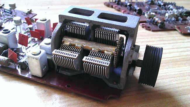
The photo shows printed circuit boards from a Chinese-made music center-radio receiver.

But this printed circuit board is from some German radio, very high quality parts.


There are a lot of variable capacitors 5-20 pF, loop coils, as well as a 4-section KPI (variable capacitor) with a mechanism for dividing the number of revolutions of the handle.

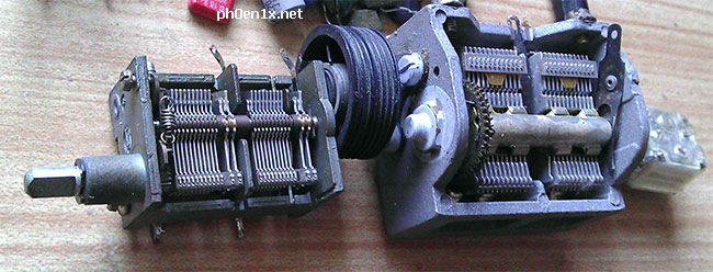
Above are printed circuit boards from a Soviet-made Speedol radio receiver, and traces of modernization are visible on it - someone soldered GT322 transistors into the input circuits.
The most interesting thing from the Speedola receiver is the KPI (variable capacitance capacitor) with a vernier mechanism. Here it is two-section, each section is from 20 to 450 picoFarads.


From imported radios, I soldered almost all electrolytic capacitors, small capacitors, diodes and part of the resistors, all variable resistors, loop coils, a ferrite rod, variable capacitors (KPI), a microphone, chokes and transistors.
TV modules SKD and SKM

As I wrote at the beginning, there is also a reception module from a transistor-integrated TV - SKD-24-M.

This is what is inside such a block - a whole radio-electronic city from different components.

Guess what it is and the pins on which pieces of copper wire are wound? - from the signature below (C26) it is not difficult to understand that this is a capacitor, and this is a capacitor for several picofarads, its capacitance can be changed either by winding it up or by unwinding the turns, so you can adjust the desired circuit to the desired frequency or parameters. I have already met a similar solution and wrote about it in the article "Strela" tube radio receiver after half a century, I did not think that it was still used somewhere in more modern equipment.
Conclusion
So many useful things can be extracted from non-working electronic equipment. electronic components. Will they help me in the future? - time will tell, some parts have already come in handy for my single-tube regenerative radio.
These parts do not take up much space, it is convenient to store them after sorting them by type, and even better by denominations. For sorting, you can glue a cassette holder out of empty matchboxes - cheap and convenient.
The coolest DP ever!
Textbooks on radio engineering, of course, are necessary and useful to read. They just don't say it all. The nature of electromagnetic waves is much broader than our ideas. The ancestors of radio a hundred years ago understood this more clearly than we do. They followed NATURE, not TEXTBOOKS. The simplest designs worked wonders for them.
I, who am so cool, have read all the books and all the textbooks on detector receivers for a hundred years, both ours and foreign ones. Then, proud of the knowledge gained, he began to CREATE different models. It was possible to build a very short, but not bad antenna - three meters in height, fifteen - the horizontal part. (The capacitance of such an antenna is very significant). I've probably tried every possible scheme there is. The following facts have been experimentally revealed:
1) Receivers work perfectly, where there is no KPI at all, and the tuning is carried out with a variometer (see one of my posts) or a ferrovariometer. Either there is no capacitor, or a permanent conder is connected in series with the antenna.
2) Matching transformer on audio frequency- this is power! The "background" of the air is listened to in 48-ohm monitor headphones (110 db/mV).
3) Diodes D9 - full g. D18 - this is cool !!! (Sometimes in "Chip and Dip. Sometimes") It's almost as cool as BAT85 (Schottky diode - always on sale). The latter, however, has a pronounced threshold, and does not hear weak stations, but it sounds great with a strong signal - high linearity and steepness of the CVC.
4) Litz wire, even domestic, on ferrite, drives. Q (When F meas \u003d 100 kHz) \u003d 110.
5) A coil wound on a cut of a fan pipe with a mounting (!!!) MGTF wire taxis doubly - the quality factor at a frequency of 100 kHz is already 120. For comparison, if it is wound enamelled, it will be somewhere around 50. Of course, this is a very indirect indicator, but I don't have a good Q - I don't have a meter. Oscilloscope too.
Somehow, in a fit of pride, I assembled a super-complex circuit with two circuits, a weak connection, a 4-diode bridge detector, and then set up this business from the GSS through the correct antenna equivalent. Everything is fine - a sensitivity of 1.5 millivolts. In practice, the 2 most powerful stations and both are quiet :(
Then I looked at the earliest detector receiver circuit - from Telefunken. 1905 I read Polyakov (you know what book I'm talking about). I thought again. I threw it out of the KPI scheme. I threw out from the circuit in general all unnecessary, in my opinion, details. The circuit took the form shown in Fig 1.
The receiver works perfectly - the restructuring is carried out by pushing the magnetic antenna into the coil (three stations at once), sufficient selectivity (we have Radio Russia and Slovo are very close, but they are tapped without overlaps).
How to explain all this - and hell knows, I'm not a theoretician. It must be assumed that the missing conder is successfully replaced by the capacitance of the antenna, as a result of which the “antenna-coil” system is tuned into resonance and acquires purely active resistance, as a result of which the current in the coil increases, and therefore the voltage on the detector increases.
In one of the models there was just an anecdotal case. It was a circuit with a coil, which had a hell of a lot of taps connected to the antenna through a switch. So, the wire leading to the KPI broke off from me. The receiver continued to work perfectly, and the stations were switched by taps :)
It has been experimentally found that the highest voltage on the detector in this configuration is provided if the load is 1 MΩ. As measured - connected through the equivalent of the GSS antenna, connected variable resistor, and measured the resulting voltage with a high-resistance voltmeter (hundreds of megohm input). A matching transformer, measured at a frequency of 1 kHz, loaded with headphones, gives a resistance of about 70 kΩ, which, of course, is also not bad, but clearly not enough. We need to dig in that direction.
There was a question about improving the scheme. American colleagues in illness advise:
- Buy from them litz for 666 cores (to hell with it!) and don’t bathe with copper
- Wind a hefty (at least 14 cm in diameter) basket spool with it
- Get the 1N34A diode (I got it, but they all turned out to be burnt: (- no luck)
- Antenna resonance - I think correctly, the resonance should be left. This will be the 1st resonant circuit, which must be connected with the second c.-l. way.
- To tune out from local powerful stations, use a filter stopper (wavetrap).
- Well, and most importantly, to make the antenna bigger - to lift it on a kite or a balloon with helium. 3 meters is nonsense. At least 10, and even all 20!