An electrical circuit is impossible without the presence of resistance in it, which is confirmed by Ohm's law. That is why the resistor is rightfully considered the most common radio component. This state of affairs suggests that knowledge of testing such elements can always come in handy when repairing electrical equipment. Consider the key issues related to how to check a conventional resistor for serviceability using a tester or multimeter.
Main stages of testing
Despite the variety of resistors, conventional elements of this class have a linear I–V characteristic, which greatly simplifies verification, reducing it to three stages:
- visual inspection;
- the radio component is tested for a break;
- compliance check is carried out.
If everything is clear with the first and second points, then there are nuances with the last, namely, it is necessary to find out the nominal resistance. Having a schematic diagram, it will not be difficult to do this, but the trouble is that modern Appliances quite rarely completed with technical documentation. You can get out of the created situation by determining the denomination by marking. We will briefly describe how to do this.
Types of markings
On components manufactured during the Soviet Union, it was customary to indicate the denomination on the body of the part (see Fig. 1). This option did not require decoding, but if the integrity of the structure was damaged or the paint burned out, there could be problems with text recognition. In such cases, one could always contact circuit diagram, which was equipped with all household appliances.
Figure 1. Resistor "ULI", on the case you can see the part rating and toleranceColor coding
Now accepted color coding, representing from three to six rings of different colors (see Fig. 2). It is not necessary to see in this the intrigues of enemies, since this way allows you to set the value even on a badly damaged part. And this is a significant factor, given that modern household electrical appliances are not equipped with circuit diagrams.
 Rice. 2. Example of color coding
 Information on decoding this designation on components is easy to find on the Internet, so it does not make sense to bring it within the framework of this article. There are also many calculator programs (including online ones) that allow you to get the necessary information.
Marking SMD elements
Surface-mounted components (e.g. smd resistor, diode, capacitor, etc.) began to be marked with numbers, but due to the small size of the parts, this information needed to be encrypted. For resistances, in most cases, a three-digit designation is adopted, where the first two are the value, and the last is the multiplier (see Fig. 3).
 Rice. 3. An example of decoding the value of the SMD resistor
 Visual inspection
Violation of the normal mode of operation causes overheating of the part, therefore, in most cases, the problem element can be identified by its appearance. This can be either a change in the color of the hull, or its complete or partial destruction. In such cases, it is necessary to replace the burnt element.
 Figure 4. A vivid example of how a resistor can burn out
 Pay attention to the photo above, the component marked "1" clearly needs to be replaced, while the neighboring parts "2" and "3" may be working, but they need to be checked.
Open circuit test
Actions are performed in the following order:

If the model of the device you are using differs from that shown in the figure, read the instructions that came with the multimeter.
- We touch the leads of the problem element on the board with the probes. If the part “does not ring” (the multimeter will show the number 1, that is, an infinitely large resistance), we can state that the test showed an open in the resistor.
Let us note that this testing can be carried out without desoldering the element from the board, but this does not guarantee a 100% result, since the tester can show the connection through other components of the circuit.
Denomination check
If the part is soldered, then this stage will allow you to guarantee its performance. For testing, we need to know the value. How to determine it by marking, it was written above.
The algorithm of our actions is as follows:

What is permission, and how important is it?
This value shows the possible deviation of this series from the specified face value. In a correctly calculated scheme, this indicator must be taken into account, or after assembly, the corresponding adjustment is made. As you understand, our friends from China do not bother with this, which has a positive effect on the cost of their goods.
The result of such a policy was shown in Figure 4, the part works for some time until the limit of its safety margin comes.
- We make a decision by comparing the readings of the multimeter with the nominal value, if the discrepancy is beyond the error, the part definitely needs to be replaced.
How to test a variable resistor?
The principle of action in this case is not very different, we will describe them using the example of the part shown in Figure 7.
 Rice. 7. Trimmer resistor (internal circuit marked with red circle)
 The algorithm is the following:
- We carry out a measurement between the legs "1" and "3" (see Fig. 7) and compare the obtained value with the nominal value.
- We connect the probes to the conclusions "2" and any of the remaining ones ("1" or "3", it does not matter).
- We rotate the tuning knob and observe the readings of the device, they should vary in the range from 0 to the value obtained in step 1.
How to check a resistor with a multimeter without soldering on the board?
This test option is valid only with low-resistance elements. Above 80-100 ohms, it is very likely that other components will interfere with the measurement. Finally, you can give an answer only by carefully studying the circuit diagram.
Continuation of the article about the beginning of electronics lessons. For those who decide to start. Detail story.
Amateur radio is still one of the most common hobbies, hobbies. If at the beginning of its glorious path, amateur radio mainly affected the design of receivers and transmitters, then with the development of electronic technology, the range of electronic devices and the circle of amateur radio interests expanded.
Of course, such complex devices as, for example, a VCR, CD player, TV or home theater system at home will not be assembled even by the most qualified radio amateur. But a lot of radio amateurs are engaged in the repair of industrial production equipment, and quite successfully.
Another direction is the design electronic circuits or refinement "to luxury" industrial devices.
The range in this case is quite large. These are devices for creating smart home”, 12 ... 220V converters for powering TVs or sound-reproducing devices from a car battery, various temperature controllers. Also very popular , and much more.
Transmitters and receivers have receded into the background, and all equipment is now simply called electronics. And now, perhaps, radio amateurs should be called something else. But historically it turned out that they simply did not come up with another name. Therefore, let there be radio amateurs.
Electronic circuit components
With all the variety of electronic devices, they consist of radio components. All components of electronic circuits can be divided into two classes: active and passive elements.
Radio components are considered active, which have the property of amplifying electrical signals, i.e. having a gain. It is easy to guess that these are transistors and everything that is made of them: operational amplifiers, logic circuits, and much more.
In a word, all those elements in which a low-power input signal controls a sufficiently powerful output. In such cases, they say that their gain (Kus) is greater than one.
Passive parts include such parts as resistors, etc. In a word, all those radio elements that have Kus within 0 ... 1! A unit can also be considered a gain: "However, it does not weaken." Let's look at the passive elements first.
Resistors
They are the simplest passive elements. Their main purpose is to limit the current in the electrical circuit. The simplest example is the inclusion of an LED, shown in Figure 1. With the help of resistors, the operating mode of the amplifier stages is also selected for various.

Figure 1. Schemes for switching on the LED
Resistor Properties
Previously, resistors were called resistances, this is just their physical property. In order not to confuse the part with its resistance property, it was renamed to resistors.
Resistance, as a property, is inherent in all conductors, and is characterized by resistivity and linear dimensions of the conductor. Well, about the same as in mechanics, specific gravity and volume.
The formula for calculating the resistance of a conductor: R = ρ*L/S, where ρ is the resistivity of the material, L is the length in meters, S is the cross-sectional area in mm2. It is easy to see that the longer and thinner the wire, the greater the resistance.
You might think that resistance is not the best property of conductors, well, it just prevents the passage of current. But in some cases, just this obstacle is useful. The fact is that when current passes through a conductor, thermal power P \u003d I 2 * R is released on it. Here P, I, R, respectively, are power, current and resistance. This power is used in various heaters and incandescent lamps.
Resistors on the circuits
All details on electrical diagrams are shown using UGO (conditional graphic symbols). UGO resistors are shown in Figure 2.
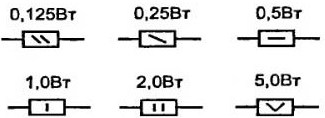
Figure 2. UGO resistors
The dashes inside the UGO indicate the power dissipation of the resistor. It should be said right away that if the power is less than required, then the resistor will heat up, and, in the end, will burn out. To calculate the power, they usually use a formula, or rather even three: P \u003d U * I, P \u003d I 2 * R, P \u003d U 2 / R.
The first formula says that the power released in a section of an electrical circuit is directly proportional to the product of the voltage drop in this section and the current through this section. If the voltage is expressed in Volts, the current in Amps, then the power will be in watts. These are the requirements of the SI system.
Next to the UGO, the nominal value of the resistance of the resistor and its serial number in the diagram: R1 1, R2 1K, R3 1.2K, R4 1K2, R5 5M1. R1 has a nominal resistance of 1Ω, R2 1KΩ, R3 and R4 1.2KΩ (the letter K or M can be used instead of a comma), R5 - 5.1MΩ.
Modern marking of resistors
Currently, resistors are marked with colored stripes. The most interesting thing is that color marking was mentioned in the first post-war magazine "Radio", published in January 1946. It was also said there that this is a new American marking. A table explaining the principle of "striped" marking is shown in Figure 3.

Figure 3. Marking resistors
Figure 4 shows SMD surface mount resistors, which are also called "chip resistors". For amateur purposes, 1206 size resistors are most suitable. They are quite large and have decent power, as much as 0.25W.
The same figure indicates that the maximum voltage for chip resistors is 200V. Resistors for conventional mounting also have the same maximum. Therefore, when a voltage is expected, for example 500V, it is better to put two resistors connected in series.
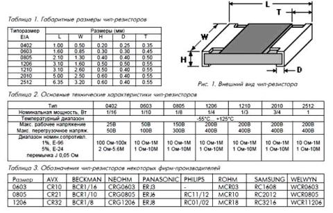
Figure 4. SMD Surface Mount Resistors
Chip resistors of the smallest sizes are produced without marking, since there is simply nowhere to put it. Starting from size 0805, a three-digit marking is placed on the "back" of the resistor. The first two are the face value, and the third is a multiplier, in the form of an exponent of the number 10. Therefore, if it is written, for example, 100, then it will be 10 * 1Ω = 10Ω, since any number to the zero degree is equal to one, the first two digits must be multiplied by exactly one .
If 103 is written on the resistor, then we get 10 * 1000 = 10 KΩ, and the inscription 474 says that we have a resistor 47 * 10,000 Ohm = 470 KΩ. Chip resistors with a tolerance of 1% are marked with a combination of letters and numbers, and the value can only be determined using a table that can be found on the Internet.
Depending on the resistance tolerance, the resistor values are divided into three rows, E6, E12, E24. The nominal values correspond to the numbers in the table shown in Figure 5.

Figure 5
The table shows that the smaller the tolerance for resistance, the more denominations in the corresponding row. If the E6 row has a tolerance of 20%, then there are only 6 denominations in it, while the E24 row has 24 positions. But these are all general purpose resistors. There are resistors with a tolerance of one percent or less, so it is possible to find any value among them.
In addition to power and nominal resistance, resistors have several more parameters, but we will not talk about them yet.
Connection of resistors
Despite the fact that there are a lot of resistor values, sometimes you have to connect them to get the required value. There are several reasons for this: the exact selection when setting up the circuit, or simply the lack of the required denomination. Basically, two resistor connection schemes are used: series and parallel. Connection diagrams are shown in Figure 6. Formulas for calculating the total resistance are also given there.
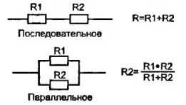
Figure 6. Resistor connection diagrams and formulas for calculating the total resistance
In the case of a series connection, the total resistance is simply the sum of the two resistances. It is as shown in the picture. In fact, there may be more resistors. Such an inclusion occurs in . Naturally, the total resistance will be greater than the largest. If these are 1KΩ and 10Ω, then the total resistance will be 1.01KΩ.
With a parallel connection, everything is just the opposite: the total resistance of two (or more resistors) will be less than the smaller one. If both resistors have the same value, then their total resistance will be equal to half of this value. You can also connect a dozen resistors in this way, then the total resistance will be just a tenth of the nominal value. For example, ten 100 ohm resistors are connected in parallel, then the total resistance is 100/10 = 10 ohms.
It should be noted that the current in parallel connection according to Kirchhoff's law is divided into ten resistors. Therefore, the power of each of them will be required ten times lower than for one resistor.
Continue reading the next article.
(fixed resistors), and in this part of the article we will talk about, or variable resistors.
Variable resistance resistors, or variable resistors are radio components whose resistance can be change from zero to nominal value. They are used as gain controls, volume and tone controls in sound reproducing radio equipment, are used for precise and smooth adjustment of various voltages and are divided into potentiometers and tuning resistors.
Potentiometers are used as smooth gain controls, volume and tone controls, serve to smoothly adjust various voltages, and are also used in servo systems, in computing and measuring devices, etc.

Potentiometer called an adjustable resistor, having two fixed outputs and one movable. The fixed terminals are located at the edges of the resistor and are connected to the beginning and end of the resistive element, which forms the total resistance of the potentiometer. The middle terminal is connected to a movable contact, which moves along the surface of the resistive element and allows you to change the resistance value between the middle and any extreme terminal.
The potentiometer is a cylindrical or rectangular case, inside which there is a resistive element made in the form of an open ring, and a protruding metal axis, which is the handle of the potentiometer. At the end of the axis, a current collector plate (contact brush) is fixed, which has reliable contact with the resistive element. Reliability of contact of the brush with the surface of the resistive layer is ensured by the pressure of the slider, made of spring materials, such as bronze or steel.


When the knob is rotated, the slider moves along the surface of the resistive element, as a result of which the resistance changes between the middle and outer terminals. And if voltage is applied to the extreme terminals, then an output voltage is obtained between them and the middle terminal.
Schematically, the potentiometer can be represented as shown in the figure below: the extreme terminals are numbered 1 and 3, the middle one is numbered 2.

Depending on the resistive element, potentiometers are divided into non-wire and wire.
1.1 Non-wire.
In non-wire potentiometers, the resistive element is made in the form horseshoe or rectangular plates of insulating material, on the surface of which a resistive layer with a certain ohmic resistance is applied.
Resistors with horseshoe resistive element have a round shape and rotational movement of the slider with a rotation angle of 230 - 270 °, and resistors with rectangular resistive element have a rectangular shape and translational movement of the slider. The most popular are resistors such as SP, OSP, SPE and SP3. The figure below shows a SP3-4 type potentiometer with a horseshoe-shaped resistive element.


The domestic industry produced potentiometers of the SPO type, in which the resistive element is pressed into an arcuate groove. The case of such a resistor is made of ceramic, and to protect against dust, moisture and mechanical damage, as well as for the purpose of electrical shielding, the entire resistor is closed with a metal cap.
Potentiometers of the SPO type have high wear resistance, are insensitive to overloads and are small in size, but they have a drawback - the difficulty of obtaining nonlinear functional characteristics. These resistors can still be found in old domestic radio equipment.

1.2. Wire.
AT wire In potentiometers, resistance is created by a high-resistance wire wound in one layer on an annular frame, along the edge of which a moving contact moves. To obtain reliable contact between the brush and the winding, the contact path is cleaned, polished, or ground to a depth of 0.25d.


The device and material of the frame is determined based on the accuracy class and the law of change in the resistance of the resistor (the law of change in resistance will be discussed below). The frames are made from a plate, which, after winding the wires, is folded into a ring, or they take a finished ring on which the winding is laid.
For resistors with an accuracy not exceeding 10 - 15%, the frames are made from a plate, which, after winding the wires, is folded into a ring. The material for the frame is insulating materials, such as getinax, textolite, fiberglass, or metal - aluminum, brass, etc. Such frames are easy to manufacture, but do not provide accurate geometric dimensions.
Frames from the finished ring are made with high precision and are used mainly for the manufacture of potentiometers. The material for them is plastic, ceramic or metal, but the disadvantage of such frames is the complexity of winding, since special equipment is required for winding it.
The winding is carried out with wires made of alloys with high electrical resistivity, for example, constantan, nichrome or manganin in enamel insulation. For potentiometers, wires made of special alloys based on noble metals are used, which have low oxidizability and high wear resistance. The wire diameter is determined based on the allowable current density.
2. Basic parameters of variable resistors.
The main parameters of resistors are: total (nominal) resistance, form of functional characteristics, minimum resistance, rated power, rotational noise level, wear resistance, parameters characterizing the behavior of the resistor under climatic influences, as well as dimensions, cost, etc. However, when choosing resistors, most often they pay attention to the nominal resistance and less often to the functional characteristic.
2.1. Rated resistance.
Rated resistance resistor is indicated on its body. According to GOST 10318-74, the preferred numbers are 1,0 ; 2,2 ; 3,3 ; 4,7 Ohm, kiloohm or megaohm.
For foreign resistors, the preferred numbers are 1,0 ; 2,0 ; 3,0 ; 5.0 Ohm, kiloohm and megaohm.
Permissible deviations of resistance from the nominal value are set within ± 30%.
The total resistance of a resistor is the resistance between terminals 1 and 3.

2.2. Form of functional characteristics.
Potentiometers of the same type may differ functional characteristic, which determines by what law the resistance of the resistor changes between the extreme and middle terminals when the resistor knob is turned. According to the form of the functional characteristic, potentiometers are divided into linear and non-linear: for linear ones, the resistance value changes in proportion to the movement of the current collector, for non-linear ones it changes according to a certain law.
There are three main laws: BUT— Linear, B– logarithmic, AT— Inverse Logarithmic (Exponential). So, for example, to control the volume in sound-reproducing equipment, it is necessary that the resistance between the middle and outer terminals of the resistive element varies according to reciprocal logarithmic law (B). Only in this case, our ear is able to perceive a uniform increase or decrease in volume.
Or in measuring instruments, for example, generators audio frequency, where variable resistors are used as frequency-setting elements, it is also required that their resistance varies according to logarithmic(B) or reciprocal logarithmic law. And if this condition is not met, then the generator scale will turn out to be uneven, which will make it difficult to accurately set the frequency.
Resistors with linear characteristic (A) are mainly used in voltage dividers as adjusting or trimmers.
The dependence of the change in resistance on the angle of rotation of the resistor knob for each law is shown in the graph below.

To obtain the desired functional characteristics, large changes in the design of potentiometers are not made. So, for example, in wirewound resistors, the wire is wound with a variable pitch, or the frame itself is made of a variable width. In non-wire potentiometers, the thickness or composition of the resistive layer is changed.

Unfortunately, adjustable resistors have relatively poor reliability and a limited lifespan. Often, owners of audio equipment that has been used for a long time have to hear rustling and crackling from the loudspeaker when turning the volume control. The reason for this unpleasant moment is a violation of the contact of the brush with the conductive layer of the resistive element or wear of the latter. The sliding contact is the most unreliable and vulnerable point of the variable resistor and is one of the main reason part failure.
3. Designation of variable resistors on the diagrams.
On the schematic diagrams, variable resistors are designated in the same way as constant ones, only an arrow is added to the main symbol, directed to the middle of the case. The arrow indicates regulation and at the same time indicates that this is the average output.

Sometimes situations arise when requirements for reliability and durability are imposed on a variable resistor. In this case, smooth control is replaced by step control, and a variable resistor is built on the basis of a switch with several positions. Constant resistance resistors are connected to the switch contacts, which will be included in the circuit when the switch knob is turned. And in order not to clutter up the circuit with the image of a switch with a set of resistors, only the variable resistor symbol with a sign is indicated step regulation. And if necessary, then additionally indicate the number of steps.

To control the volume and tone, the recording level in sound reproducing stereo equipment, to control the frequency in signal generators, etc. apply dual potentiometers, the resistance of which changes simultaneously when turning general axis (engine). On the diagrams, the symbols of the resistors included in them are placed as close as possible to each other, and the mechanical connection that ensures the simultaneous movement of the sliders is shown either by two solid lines or by one dashed line.

The belonging of the resistors to one dual block is indicated according to their positional designation in the electrical circuit, where R1.1 is the first resistor of the dual variable resistor R1 in the circuit, and R1.2- second. If the symbols of the resistors are at a great distance from each other, then the mechanical connection is indicated by segments of the dotted line.

The industry produces dual variable resistors, in which each resistor can be controlled separately, because the axis of one passes inside the tubular axis of the other. Such resistors do not have a mechanical connection that ensures simultaneous movement, therefore it is not shown on the diagrams, and belonging to a dual resistor is indicated according to the reference designation in the electrical circuit.
In portable consumer audio equipment, such as receivers, players, etc., variable resistors are often used with a built-in switch, the contacts of which are used to supply power to the device circuit. For such resistors, the switching mechanism is combined with the axis (knob) of the variable resistor and, when the handle reaches the extreme position, acts on the contacts.

As a rule, in the diagrams, the switch contacts are located near the power source in the break of the supply wire, and the connection between the switch and the resistor is indicated by a dotted line and a dot, which is located at one of the sides of the rectangle. This means that the contacts close when moving away from the point, and open when moving towards it.
4. Trimmer resistors.
Trimmer Resistors are a kind of variables and are used for one-time and fine-tuning of radio-electronic equipment in the process of its installation, adjustment or repair. As trimmers, both variable resistors of the usual type with a linear functional characteristic, the axis of which is made “under the slot” and equipped with a locking device, and resistors of a special design with increased accuracy in setting the resistance value are used.

For the most part, tuning resistors of a special design are made in a rectangular shape with flat or ring resistive element. Resistors with a flat resistive element ( a) have a translational movement of the contact brush, carried out by a micrometric screw. For resistors with a ring resistive element ( b) the movement of the contact brush is carried out by a worm gear.

For heavy loads, open cylindrical resistor designs are used, for example, PEVR.

On the circuit diagrams, trimming resistors are denoted in the same way as variables, only instead of the regulation sign, the trimming regulation sign is used.

5. The inclusion of variable resistors in an electrical circuit.
In electrical circuits, variable resistors can be used as rheostat(adjustable resistor) or as potentiometer(voltage divider). If it is necessary to regulate the current in the electrical circuit, then the resistor is turned on with a rheostat, if the voltage is turned on, then the potentiometer is turned on.
When the resistor is turned on rheostat involve the middle and one extreme conclusion. However, such inclusion is not always preferable, since in the process of regulation, an accidental loss of contact with the resistive element by the middle terminal is possible, which will entail an undesirable break in the electrical circuit and, as a result, a possible failure of the part or electronic device generally.

To prevent accidental breakage of the circuit, the free terminal of the resistive element is connected to a movable contact so that if the contact is broken electrical circuit always remained closed.

In practice, the inclusion of a rheostat is used when they want to use a variable resistor as an additional or current-limiting resistance.
When the resistor is turned on potentiometer all three outputs are used, which allows it to be used as a voltage divider. Take, for example, a variable resistor R1 with such a nominal resistance that will extinguish almost all the voltage of the power source coming to the lamp HL1. When the resistor knob is unscrewed to the uppermost position according to the diagram, then the resistance of the resistor between the upper and middle terminals is minimal and all the voltage of the power source is supplied to the lamp, and it glows with full heat.

As the resistor knob is moved down, the resistance between the upper and middle terminals will increase, and the voltage on the lamp will gradually decrease, which is why it will not shine at full glow. And when the resistance of the resistor reaches its maximum value, the voltage on the lamp drops to almost zero, and it goes out. It is by this principle that the volume is regulated in sound-reproducing equipment.
The same voltage divider circuit can be depicted a little differently, where the variable resistor is replaced by two constants R1 and R2.

Well, basically, that's all I wanted to say about variable resistance resistors. In the final part, we will consider a special type of resistors, the resistance of which changes under the influence of external electrical and non-electrical factors -.
Good luck!
Literature:
V. A. Volgov - "Details and components of radio-electronic equipment", 1977
V. V. Frolov - "Language of radio circuits", 1988
M. A. Zgut - " Conventions and radio circuits", 1964
Often during an external examination, damage to the varnish or enamel coating can be detected. A resistor with a charred surface or rings on it is also faulty. A slight darkening of the varnish coating allowed for such resistors should be checked for the resistance value. Permissible deviation from the nominal value should not exceed ±20%. The deviation of the resistance value from the nominal value in the direction of increase is observed during long-term operation of high-resistance resistors (more than 1 MΩ).
In some cases, a break in the conductive element does not cause any changes appearance resistor. Therefore, the resistors are checked for compliance with their nominal values using an ohmmeter. Before measuring the resistance of resistors in the circuit, turn off the receiver and discharge the electrolytic capacitors. When measuring, it is necessary to ensure reliable contact between the terminals of the tested resistor and the terminals of the device. In order not to shunt the device, do not touch the metal parts of the ohmmeter probes with your hands. The value of the measured resistance must correspond to the value indicated on the resistor case, taking into account the tolerance corresponding to the class of this resistor and the intrinsic error of the measuring device. For example, when measuring the resistance of a resistor of class I accuracy using the Ts-4324 instrument, the total error during the measurement can reach ±15% (resistor tolerance ±5% plus instrument error ±10). If the resistor is tested without. soldering it out of the circuit, then it is necessary to take into account the influence of shunt circuits.
The most common malfunction in resistors is the burnout of the conductive layer, which can be caused by the passage of an unacceptably large current through the resistor as a result of various short circuits in the installation or breakdown of the capacitor. Wirewound resistors are much less likely to fail. Their main malfunctions (breakage or burnout of the wire) are usually found using an ohmmeter.
Variable resistors (potentiometers) most often have a violation of the contact of the movable brush with the conductive elements of the resistor. If such a potentiometer is used in a radio receiver to adjust the volume, then when turning its axis, cods are heard in the head of the dynamic loudspeaker. There are also breaks, wear or damage to the conductive layer.
The serviceability of the potentiometers is determined with an ohmmeter. To do this, connect one of the ohmmeter probes to the middle petal of the potentiometer, and the second probe to one of the extreme petals. The axis of the regulator with each such connection is very slowly rotated. If the potentiometer is working, then the ohmmeter needle moves along the scale smoothly, without jitter and jerks. The jitter and jerks of the arrow indicate poor contact between the brush and the conductive element. If the ohmmeter needle does not deviate at all, this means that the resistor is faulty. It is recommended to repeat such a check by switching the second probe of the ohmmeter to the second extreme lobe of the resistor to make sure that this output is also working. A defective potentiometer must be replaced with a new one or repaired if possible. To do this, open the case of the potentiometer and thoroughly wash the conductive element with alcohol and apply a thin layer of machine oil. Then it is collected and the reliability of the contact is checked again.
Resistors that are deemed unsuitable are usually replaced with serviceable ones, the values of which are selected so that they correspond to the receiver's circuit diagram. In the absence of a resistor with the appropriate resistance, it can be replaced by two (or several) connected in parallel or in series. When two resistors are connected in parallel, the total resistance of the circuit can be calculated by the formula
![]()
where P is the power dissipated by the resistor, W; U is the voltage across the resistor. AT; R is the resistance value of the resistor; Ohm.
It is advisable to take a resistor with a slightly higher dissipation power (by 30,..40%) than that obtained in the calculation. In the absence of a resistor of the required power, you can select several smaller resistors. power and connect them to each other in parallel or in series so that their total resistance is equal to the one being replaced, and the total power is not lower than the required one.
When determining interchangeability various types fixed and variable resistors for the latter also take into account the characteristics of the change in resistance from the angle of rotation of its axis. The choice of the characteristics of the change of the potentiometer is determined by its circuit purpose. For example, in order to obtain a uniform volume control of the radio receiver, you should select the potentiometers of group B (with an exponential dependence of the change in resistance), and in the tone control circuits - group A.
When replacing failed resistors of the BC type, it is possible to recommend MLT type resistors of the appropriate dissipation power, which have smaller dimensions and better moisture resistance. The rated power of the resistor and its accuracy class are not significant in the circuits of the control grids of lamps and collectors of low power transistors.
When assembling any device, even the simplest one, radio amateurs often have problems with radio components, it happens that they cannot get some kind of resistor of a certain value, a capacitor or a transistor ... in this article I want to talk about replacing radio components in circuits, which radio elements can be replaced with what and which ones are impossible, how they differ, what types of elements are used in which nodes, and much more. Most radio components can be replaced with similar ones with similar parameters.
Let's start with resistors.
So, you probably already know that resistors are the most basic elements of any circuit. Without them, no circuit can be built, but what if you do not have the necessary resistances for your circuit? Consider specific example, take for example the scheme of the LED flasher, here it is in front of you:

In order to understand which resistors can be changed within what limits, we need to understand what they generally affect. Let's start with the resistors R2 and R3 - they affect (together with the capacitors) the blinking frequency of the LEDs, i.e. you can guess that by changing the resistance up or down, we will change the blinking frequency of the LEDs. Therefore, these resistors in this circuit can be replaced with close ones at face value if you do not have those indicated in the circuit. To be more precise, in this circuit, resistors can be used, let's say from 10 kOhm to 50 kOhm. As for the resistors R1 and R4, the frequency of the generator also depends on them to some extent, in this circuit they can be set from 250 to 470 ohms. There is one more thing, after all, LEDs are for different voltages, if LEDs for a voltage of 1.5 volts are used in this circuit, and we will put an LED there on more voltage- we will burn them very dimly, therefore, we will need to put the resistors R1 and R4 on a lower resistance. As you can see, the resistors in this circuit can be replaced with other, close values. Generally speaking, this applies not only to this circuit, but also to many others, if you didn’t have a 100kΩ resistor when assembling the circuit, you can replace it with 90 or 110kΩ, the smaller the difference, the better it is not worth putting 10kΩ instead of 100kΩ , otherwise the circuit will not work correctly or at all, any element may fail. By the way, do not forget that resistors have a permissible deviation in value. Before changing the resistor to another, carefully read the description and the principle of operation of the circuit. In precision measuring instruments, you should not deviate from the values \u200b\u200bspecified in the circuit.
Now, as for the power, the more powerful the resistor, the thicker it is, it’s impossible to put 0.125 watts instead of a powerful 5 watt resistor, at best it will get very hot, at worst it will simply burn out.
And to replace a low-power resistor with a more powerful one - you are always welcome, nothing will come of it, only powerful resistors are larger, you will need more space on the board, or you will have to put it vertically.
Do not forget about parallel and series connection of resistors, if you need a 30kΩ resistor, you can make it from two 15kΩ resistors connected in series.
In the circuit that I gave above, there is a tuning resistor. Of course, it can be replaced with a variable, there is no difference, the only thing is that the trimmer will have to be twisted with a screwdriver. Is it possible to change trimmers and variable resistors in circuits to ones close in value? In general, yes, in our circuit it can be set to almost any denomination, at least 10kOhm, at least 100kOhm - the regulation limits will simply change, if we set 10kOhm, by rotating it we will change the blinking frequency of the LEDs faster, and if we set 100kOhm., the blinking frequency adjustment will be be made smoother and "longer" than with 10k. In other words, at 100 kΩ, the adjustment range will be wider than at 10 kΩ.
But replacing variable resistors with cheaper trimmers is not worth it. Their engine is rougher and with frequent use the conductive layer is severely scratched, after which, when the engine is rotated, the resistance of the resistor can change abruptly. An example of this is wheezing in the speakers when the volume is changed.
You can read more about the types and types of resistors.
Now let's talk about capacitors, they come in different types, types and of course capacities. All capacitors differ in such basic parameters as nominal capacity, operating voltage and tolerance. In radio electronics, two types of capacitors are used, these are polar and non-polar. The difference between polar capacitors and non-polar ones is that polar capacitors must be included in the circuit strictly observing the polarity. Capacitors in shape are radial, axial (the terminals of such capacitors are on the side), with threaded terminals (usually these are high-capacity or high-voltage capacitors), flat, and so on. There are pulse, noise suppression, power, audio capacitors, general purpose, etc.

Where are capacitors used?
Ordinary electrolytic filters are used in power supply filters, sometimes ceramics are also installed (they serve to filter and smooth the rectified voltage), high-frequency electrolytes are used in switching power supply filters, ceramics in power circuits, and ceramics in non-critical circuits.
On a note!
Electrolytic capacitors usually have a large leakage current, and the capacitance error can be 30-40%, i.e. The capacity indicated on the bank, in reality, can be very different. The nominal capacitance of such capacitors decreases as they are used. The most common defect of old electrolytic capacitors is capacitance loss and increased leakage, such capacitors should not be used further.
We will return to our multivibrator (flasher) circuit, as you can see there are two electrolytic polar capacitors, they also affect the blinking frequency of the LEDs, the larger the capacitance, the slower they will flash, the smaller the capacitance, the faster they will flash.
In many devices and devices, you can’t “play” with the capacitances of capacitors like that, for example, if the circuit costs 470 microfarads, then you should try to put 470 microfarads, or in parallel 2 capacitors of 220 microfarads. But again, depending on which node the capacitor is located and what role it performs.
Consider an example on a low frequency amplifier:

As you can see, there are three capacitors in the circuit, two of which are not polarized. Let's start with capacitors C1 and C2, they are at the input of the amplifier, a sound source passes / is fed through these capacitors. What happens if instead of 0.22 uF we put 0.01 uF? Firstly, the sound quality will deteriorate slightly, and secondly, the sound in the speakers will become noticeably quieter. And if we put 1 uF instead of 0.22 uF, then at high volumes we will have wheezing in the speakers, the amplifier will be overloaded, it will heat up more, and the sound quality may deteriorate again. If you look at the circuit of some other amplifier, you can see that the input capacitor can be 1 uF or even 10 uF. It all depends on each specific case. But in our case, 0.22 uF capacitors can be replaced with ones that are close in value, for example, 0.15 uF or better than 0.33 uF.
So, we got to the third capacitor, we have it polar, it has a plus and a minus, it is impossible to confuse the polarity when connecting such capacitors, otherwise they will heat up, which is even worse, they will explode. And they bang very, very strongly, they can lay their ears. Capacitor C3 with a capacity of 470 microfarads is in our power circuit, if you don’t already know, then I’ll say that in such circuits, and for example in power supplies, the larger the capacitance, the better.
Now every house has speakers, maybe you noticed that if you listen to music loudly, the speakers wheeze, and the LED in the speaker also flashes. This usually just means that the capacitance of the capacitor in the power supply filter circuit is small (+ transformers are weak, but I won’t talk about that). Now back to our amplifier, if we put 10 uF instead of 470 uF - this is almost the same as not putting a capacitor at all. As I said, in such circuits, the larger the capacitance, the better, to be honest, in this circuit 470 microfarads is very small, you can put all 2000 microfarads.
It is impossible to set the capacitor to a lower voltage than it is in the circuit, because of this it will heat up and explode, if the circuit operates on 12 volts, then you need to set the capacitor to 16 volts, if the circuit operates on 15-16 volts, then it is better to put the capacitor on 25 volts.
What to do if there is a non-polar capacitor in the circuit you are assembling? A non-polar capacitor can be replaced with two polar ones, by including them in series in the circuit, the pluses are connected together, while the capacitance of the capacitors must be twice as large as indicated in the diagram.
Never discharge capacitors by shorting their outputs! You should always discharge through a high-resistance resistor, and do not touch the capacitor terminals, especially if it is high-voltage.

On almost all polar electrolytic capacitors, a cross is pressed into the upper part, this is a kind of protective notch (often called a valve). If such a capacitor is fed AC voltage or exceed allowable voltage, then the capacitor will start to get very hot, and the liquid electrolyte inside it will begin to expand, after which the capacitor bursts. In this way, the explosion of the capacitor is often prevented, with the electrolyte flowing out.

In this regard, I want to give a little advice, if after repairing any equipment, after replacing capacitors, you turn it on for the first time (for example, electrolytic capacitors are changed in old amplifiers), close the lid and keep your distance, God forbid that bangs.
Now the question is for backfilling: is it possible to include a non-polar capacitor for 230 volts in a 220 volt network? What about 240? Just please, do not immediately grab such a capacitor and do not plug it into a power outlet!
For diodes, the main parameters are the allowable forward current, reverse voltage and forward voltage drop, sometimes you still need to pay attention to the reverse current. Such parameters of the replacement diodes should be no less than those of the replaced ones.

In low-power germanium diodes, the reverse current is much greater than in silicon ones. The forward voltage drop of most germanium diodes is about half that of similar silicon diodes. Therefore, in circuits where this voltage is used to stabilize the operating mode of the circuit, for example, in some final sound amplifiers, replacing diodes with a different type of conductivity is not allowed.
For rectifiers in power supplies, the main parameters are reverse voltage and maximum admissible current. For example, at currents of 10A, diodes D242 ... D247 and similar can be used, for a current of 1 ampere you can KD202, KD213, from imported ones these are diodes of the 1N4xxx series. Of course, it is impossible to put a 1 ampere diode instead of a 5 ampere diode, on the contrary it is possible.
In some schemes, for example impulse blocks Schottky diodes are often used for power supply, they operate at higher frequencies than conventional diodes, you should not replace such diodes with conventional diodes, they will quickly fail.
In many simple circuits, you can put any other diode as a replacement, the only thing is, do not confuse the output, you should be careful about this, because. diodes can also burst or smoke (in the same power supplies) if you confuse the anode with the cathode.
Can diodes (including Schottky diodes) be connected in parallel? Yes, you can, if two diodes are connected in parallel, the current flowing through them can be increased, the resistance, the voltage drop across the open diode and the power dissipation are reduced, therefore, the diodes will heat up less. Diodes can only be paralleled with the same parameters, from one box or batch. For low-power diodes, I recommend installing the so-called "current-equalizing" resistor.
Transistors are divided into low power, medium power, high power, low frequency, high frequency, etc. When replacing, you need to take into account the maximum allowable emitter-collector voltage, collector current, power dissipation, and the gain.

The replacement transistor, firstly, must belong to the same group as the one being replaced. For example, low power at low frequency or high power at medium frequency. Then a transistor of the same structure is selected: p-p-p or p-p-p, a field-effect transistor with a p-channel or n-channel. Next, the values \u200b\u200bof the limiting parameters are checked; for the replacing transistor, they must be no less than for the replaced one.
Silicon transistors are recommended to be replaced only with silicon transistors, germanium transistors with germanium transistors, bipolar transistors with bipolar ones, etc.
Let's get back to the circuit of our flasher, two transistors of the n-p-n structure are used there, namely KT315, these transistors can be easily replaced with KT3102, or even with an old MP37, suddenly someone has some Transistors that can work in this circuit very, very much.
Do you think KT361 transistors will work in this circuit? Of course not, KT361 transistors have a different structure, p-n-p. By the way, the analogue of the transistor KT361 is KT3107.
In devices where transistors are used in key modes, such as control stages for relays, LEDs, logic circuits, etc... transistor selection does not matter. of great importance, choose a similar power, and close in parameters.
In some schemes, for example, KT814, KT816, KT818 or KT837 can be replaced with each other. Take for example transistor amplifier, its diagram is below.

The output stage is built on KT837 transistors, they can be replaced with KT818, but you should not change it with KT816, it will heat up very much and quickly fail. In addition, the output power of the amplifier will decrease. Transistor KT315, as you probably guessed, is changing to KT3102, and KT361 to KT3107.
A powerful transistor can be replaced by two low-power ones of the same type, they are connected in parallel. When connected in parallel, transistors should be used with close gain values, it is recommended to install equalizing resistors in the emitter circuit of each, depending on the current: from tenths of an ohm at high currents, to units of ohms at low currents and powers. AT field effect transistors such resistors are usually not installed, because. they have a positive channel TCR.
I think we’ll finish this, in conclusion I want to say that you can always ask Google for help, it will always tell you, give tables for replacing radio components with analogues. Good luck!