
Surely you have already seen indicators - "eights". This is the seven-segment LED indicator that displays the numbers from 0 to 9, as well as the decimal point ( D.P.- Decimal point) or a comma.
Structurally, such a product is an assembly of LEDs. Each assembly LED illuminates its character segment.
Depending on the model, the assembly may consist of 1 - 4 seven-segment groups. For example, the ALS333B1 indicator consists of one seven-segment group, which is capable of displaying only one digit from 0 to 9.
But the KEM-5162AS LED indicator already has two seven-segment groups. It is two-dimensional. The photo below shows different LED seven-segment indicators.

There are also indicators with 4 seven-segment groups - four-digit (in the photo - FYQ-5641BSR-11). They can be used in homemade electronic watches.

How are seven-segment indicators indicated on the diagrams?
Since the seven-segment indicator is a combined electronic device, then its image on the diagrams differs little from its appearance.

One has only to pay attention to the fact that each output corresponds to a specific character segment to which it is connected. There is also one or more terminals of a common cathode or anode, depending on the model of the device.
Features of seven-segment indicators.
Despite the seeming simplicity of this detail, it has its own peculiarities.
Firstly, LED seven-segment indicators come with a common anode and a common cathode. This feature should be considered when buying it for a home-made design or device.
Here, for example, is the pinout of a 4-digit indicator already familiar to us FYQ-5641BSR-11.

As you can see, the anodes of the LEDs of each digit are combined and brought to a separate output. The cathodes of the LEDs that belong to the sign segment (for example, G) are linked together. A lot depends on the connection scheme of the indicator (with a common anode or cathode). If you look at circuit diagrams instruments using seven-segment indicators, it will become clear why this is so important.
In addition to small indicators, there are large and even very large ones. They can be seen in public places, usually in the form wall clock, thermometers, informers.
In order to increase the size of the numbers on the scoreboard and at the same time maintain sufficient brightness for each segment, several LEDs are used, connected in series. Here is an example of such an indicator - it fits in the palm of your hand. it FYS-23011-BUB-21.

One of its segments consists of 4 LEDs connected in series.

To illuminate one of the segments (A, B, C, D, E, F or G), you need to apply a voltage of 11.2 volts to it (2.8V for each LED). It is possible and less, for example, 10V, but the brightness will also decrease. The exception is the decimal point (DP), its segment consists of two LEDs. It needs only 5 - 5.6 volts.

Also in nature there are two-color indicators. They are embedded, for example, red and green LEDs. It turns out that two indicators are built into the case, but with LEDs of a different glow color. If you apply voltage to both circuits of the LEDs, you can get a yellow glow of the segments. Here is a wiring diagram for one of these two-color indicators (SBA-15-11EGWA).

If you switch conclusions 1 ( RED) and 5 ( GREEN) to "+" power supply through the key transistors, then you can change the color of the glow of the displayed numbers from red to green. And if you connect pins 1 and 5 at the same time, then the color of the glow will be orange. This is how you can mess around with indicators.
Management of seven-segment indicators.
To control seven-segment indicators in digital devices, shift registers and decoders are used. For example, a widely used decoder for controlling indicators of the ALS333 and ALS324 series is a microcircuit K514ID2 or K176ID2. Here is an example.
And to control modern imported indicators, shift registers are usually used. 74HC595. In theory, you can control the segments of the scoreboard directly from the outputs of the microcontroller. But such a scheme is rarely used, since this requires using quite a few pins of the microcontroller itself. Therefore, shift registers are used for this purpose. In addition, the current consumed by the LEDs of the sign segment may be greater than the current that can be provided by the ordinary output of the microcontroller.
To control large seven-segment indicators, such as FYS-23011-BUB-21, specialized drivers are used, for example, a microcircuit MBI5026.
What's inside a seven-segment indicator?
Well, some delicious food. Any electronics engineer would not be such if he was not interested in the "insides" of radio components. This is what is inside the ALS324B1 indicator.

The black squares on the base are LED crystals. You can also see the gold jumpers that connect the crystal to one of the conclusions. Unfortunately, this indicator will no longer work, since these same jumpers were cut off. But on the other hand, we can see what is hidden behind the decorative panel of the scoreboard.
Seven-segment indicator: operation programming
In the first part of the article about, a description of the indicator and how to connect it to the microcontroller was given. In the second and third parts, we will sequentially go through all the stages of organizing the work of a microcontroller with an indicator and creating a program, the result of which will be a really working design.
Converting the binary code of a decimal number to the code of a seven-segment indicator
Let's take another look at the diagram for connecting a seven-segment indicator to a microcontroller: 
On this diagram port pins PB0…..PB7 connected to the terminals of the indicator in a certain sequence. The output PB0 corresponds to the segment "A" and then, respectively, along serial number port pin and indicator pin alphabetically, with the decimal point "dp" connected to the PB7 port pin. Now and further we will consider connection diagrams for indicators with a common cathode, and if necessary, I will insert additions for an indicator with a common anode.
In order to highlight a certain number on the indicator, it is necessary to install on the corresponding pins of the microcontroller port logical unit

In the figure above, black numbers from 0 to 7 are port pins, green Latin letters are LED indicator pins, red zeros are logic levels at the port outputs (in this case, logic level “0”). In order, for example, to highlight the number “4” on the indicator and light up the decimal point, we need to apply a logical 1 to the indicator pins B, C, F, G and dp, which corresponds to the supply of a logical unit to port pins 1,2,5 ,6 and 7:

Therefore, the first thing we need to do is to determine the correspondence to each decimal digit of a binary number that must be output to the output of the microcontroller port to ignite the corresponding segments of the indicator.
For the "four" we have already defined such a combination = 1110 0110, which corresponds to the hexadecimal number 66h, we also define it for the remaining digits:

The operation we have done is called binary code translation decimal number to the seven-segment indicator code .
This table is given for seven-segment indicators with a common cathode (the indicator segment is lit by the logic level "1"). For indicators with a common anode (the indicator segment is lit by the logic level "0"), the binary codes must be inverted (change 0 to 1, and vice versa) and recalculate the corresponding values in hexadecimal system.
Programming a single-digit seven-segment indicator
The use of a single-digit indicator in the design may be required in different cases. For example, we assemble a code lock and there is a need to display the number corresponding to the pressed button, or in the security alarm to display the number of the triggered sensor. So the scope of single-digit indicators is decent.
We will arrange the output of numbers on a single-digit indicator in the form of a subroutine: "Information output to a single-digit seven-segment LED indicator"
, so that this subroutine can then be used in any program with minimal changes.
Subroutine algorithm:
1. Indicator initialization (subroutine)
- setting the port to which the indicator is connected to display information
- writing seven-segment indicator codes corresponding to decimal digits in certain cells memory
This subroutine must be called separately from the main program
2. Entering the main subroutine
3. Main body
- read the current number
- determine which code of the seven-segment indicator corresponds to the current decimal digit
- write a specific indicator code to the microcontroller port
4. Exit the subroutine
To design a program as a subprogram, we need to do a number of actions:
1.
We assign a name to the indicator initialization subroutine - Ini_Indicator_1(for example)
2.
Assign a name to the main subroutine - Indicator_1
3.
We assign names to the SRAM variables in which the codes of the seven-segment indicator will be stored, for example:
— D0(for the number 0, and so on), D1, D2, D3, D4, D5, D6, D7, D8, D9
- assign the name of the variable in which the address of the memory cell (D0) with the code of the first digit (0) will be stored - D0_9
4.
Assign the name of the variable that will store the current figure that needs to be displayed on the indicator. The main program will write the calculated data (numbers) to this variable, which we display on the indicator - Data(for example).
Here is how, for example, in Algorithm Builder (other examples are also for this program), variable names are declared in program memory (RAM, SRAM):
The "Name" column lists all variable names. In the column "Address" the entry "@D0_9" means that the variable D0_9 stores the address of the first variable (D0)
The indicator initialization subroutine (the subroutine is called from the main program before calling the subroutine for outputting information to the indicator):

And now let's see the main part of the program and decrypt it:

The main program wrote to the variable we assigned Data the current digit (for example, the digit 6 ) and called the subroutine to display it on the indicator Indicator_1.
Subroutine operation:
— The content of the variable Data is written to the working register R20, now in register number 6(working register can be any)
- Let's say the first variable with the digit code 0
we have in the memory cell at the address 100
. In fact, we do not know the addresses of the memory cells where the values are stored. D0…D9, but they exactly follow each other. So the variable was assigned D0_9, which, as we assigned, stores the address of the memory cell D0(in this moment address = 100
).
- With the following command:
@D0_9 —> Y we load in double register Y variable address D0 and we get that in the register Y number entered - 100
.
- With the following command:
Y+R20 we add up the number 100
with number 6
, result = 106
while being stored in double register Y.
- With the following command:
[Y] -> R20 we write the contents of the memory cell located at the address, which is written in double register Y (106), and at this address we have a variable memory cell D6. Now in working register R20 written number 7Dh — seven-segment indicator code for displaying the number 6
.
- With the following command:
R20 —> PortB we output content R20 to port PB — flash the number 6
- We return from the subroutine

One of the very important elements of digital technology, and especially in computers and control systems, are encoders and decoders.
When we hear the word encoder or decoder, phrases from spy movies come to mind. Something like: decrypt the dispatch and encrypt the reply.
There is nothing wrong with this, since encryption machines of our and foreign residencies use encoders and decoders.
Encoders.
Thus, the encoder (encoder) is electronic device, in this case, a microcircuit that converts the code of one number system to the code of another system. The most widely used in electronics are encoders that convert a positional decimal code into parallel binary. This is how the encoder can be indicated on the circuit diagram.
For example, let's imagine that we are holding an ordinary calculator in our hands, which is now used by any student.

Since all operations in the calculator are performed with binary numbers(remember the basics of digital electronics), then after the keyboard there is an encoder that converts the entered numbers into binary form.
All buttons of the calculator are connected to a common wire and, by pressing, for example, button 5 at the input of the encoder, we immediately get the binary form of this number at its output.
Of course, the encoder of the calculator has a larger number of inputs, since in addition to numbers, some other symbols of arithmetic operations must be entered into it, therefore, not only numbers in binary form, but also commands are removed from the outputs of the encoder.
If we consider the internal structure of the encoder, then it is easy to make sure that it is made on the simplest basic logic elements.
In all control devices that operate on binary logic, but for the convenience of the operator have a decimal keyboard, encoders are used.
Decoders.
Decoders belong to the same group, only they work exactly the opposite. They convert parallel binary to positional decimal. The conditional graphic designation on the diagram may be as follows.

Or like this.

Speaking more fully about decoders, it is worth saying that they can convert binary code to different systems calculus (decimal, hexadecimal, etc.). It all depends on specific purpose and purpose of the microcircuit.
The simplest example. You have seen a digital seven-segment indicator more than once, for example, an LED. It displays decimal digits and numbers to which we are accustomed since childhood (1, 2, 3, 4...). But, as you know, digital electronics works with binary numbers, which are a combination of 0 and 1. What converted the binary code to decimal and submitted the result to a digital seven-segment indicator? You probably already guessed that the decoder did it.
The work of the decoder can be evaluated live if you assemble a simple circuit that consists of a decoder chip K176ID2 and an LED seven-segment indicator, which is also called the "eight". Take a look at the diagram, it is easier to understand how the decoder works. A solderless breadboard can be used to quickly assemble the circuit.

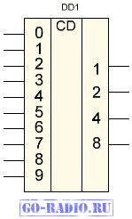
For reference. The K176ID2 microcircuit was developed to control a 7-segment LED indicator. This chip is capable of converting binary code from 0000 before 1001 , which corresponds to decimal digits from 0 to 9 (one decade). The rest, older combinations are simply not displayed. Conclusions C, S, K are auxiliary.
The K176ID2 chip has four inputs (1, 2, 4, 8). They are sometimes also referred to D0-D3. These inputs are given a parallel binary code (for example, 0001). In this case, the binary code has 4 bits. The microcircuit converts the code so that the outputs ( a-g) signals appear, which form decimal digits and numbers to which we are accustomed on the seven-segment indicator. Since the K176ID2 decoder is capable of displaying decimal digits in the range from 0 to 9, we will only see them on the indicator.
4 toggle switches (S1 - S4) are connected to the inputs of the K176ID2 decoder, with the help of which a parallel binary code can be applied to the decoder. For example, when closing the toggle switch S1 a logical unit is applied to the 5th output of the microcircuit. If you open the contacts of the toggle switch S1- this will correspond to a logical zero. With the help of toggle switches, we can manually set the logic 1 or 0 at the inputs of the microcircuit. I think everything is clear with this.
The diagram shows how the code 0101 is applied to the inputs of the decoder DD1. The number 5 will be displayed on the LED indicator. If only the toggle switch S4 is closed, the number 8 will be displayed on the indicator. To write a number from 0 to 9 in a binary code, four digits are enough: a 3 * 8 + a 2 * 4 + a 1 * 2 + a 0 * 1, where a 0 - a 3, are numbers from the number system (0 or 1).
Let's represent the number 0101 in decimal form 0101 = 0*8 + 1*4 + 0*2 + 1*1 = 4 + 1 = 5 . Now let's look at the diagram and see that the weight of the digit corresponds to the number that 0 or 1 is multiplied by in the formula.
A decoder based on TTL technology - K155ID1 was used at one time to control a gas discharge digital indicator type IN8, IN12, which were in great demand in the 70s, since LED low-voltage indicators were still very rare.
Everything changed in the 80s. It was possible to freely purchase seven-segment LED matrix(indicators) and a boom in the assembly of electronic clocks swept among radio amateurs. Homemade Digital Watch not collected for the house only lazy.
In this article we will talk about digital display.
Seven-segment LED indicators are designed to display Arabic numerals from 0 to 9 (Fig. 1).
Such indicators are single-digit, which display only one number, but there can be more seven-segment groups combined in one case (multi-digit). In this case, the numbers are separated by a decimal point (Fig. 2)

Fig.2.
The indicator is called seven-segment due to the fact that the displayed symbol is built from separate seven segments. Inside the case of such an indicator there are LEDs, each of which illuminates its own segment.
It is problematic to display letters and other symbols on such indicators, therefore 16-segment indicators are used for these purposes.
There are two types of LED indicators.
In the first of them, all cathodes, i.e. the negative terminals of all the LEDs are combined together and the corresponding output on the case is allocated for them.
The remaining outputs of the indicator are connected to the anode of each of the LEDs (Fig. 3, a). Such a circuit is called a "common cathode circuit".
There are also indicators in which the LEDs of each of the segments are connected according to the scheme with a common anode (Fig. 3, b).

Fig.3.
Each segment is labeled with a corresponding letter. Figure 4 shows their location. 
Fig.4.
As an example, consider a two-digit seven-segment indicator GND-5622As-21 of a red glow. By the way, there are other colors, depending on the model.
Using a three-volt battery, you can turn on the segments, and if you combine a group of pins into a bunch and apply power to them, you can even display numbers. But this method is inconvenient, so shift registers and decoders are used to control seven-segment indicators. Also, often, the indicator outputs are connected directly to the outputs of the microcontroller, but only when indicators with low current consumption are used. Figure 5 shows a fragment of the circuit using PIC16F876A.

Fig.5.
For management seven-segment indicator the K176ID2 decoder is often used.
This microcircuit is capable of converting the binary code consisting of zeros and ones into decimal digits from 0 to 9.
To understand how it all works, you need to collect a simple circuit(Fig. 6). The K176ID2 decoder is made in the DIP16 package. It has 7 output pins (pins 9 - 15), each dedicated to a specific segment. Point management is not provided here. The microcircuit also has 4 inputs (pins 2 - 5) for supplying a binary code. The 16th and 8th pins are supplied with plus and minus power, respectively. The remaining three conclusions are auxiliary, I will talk about them a little later.

Fig.6.
DD1 - K176ID2
R1 - R4 (10 - 100 kOhm)
HG1-GND-5622As-21
There are 4 toggle switches in the circuit (any buttons are possible), when you press them, a logical unit is supplied to the decoder inputs from the power plus. By the way, the microcircuit itself is powered by a voltage of 3 to 15 volts. AT this example the whole circuit is powered by a 9-volt "crown".
There are also 4 resistors in the circuit. These are the so-called pull-up resistors. They are needed to guarantee a low level at the logical input, in the absence of a signal. Without them, the readings on the indicator may not be displayed correctly. It is recommended to use the sameresistance from 10 kOhm to 100 kOhm.
In the diagram, pins 2 and 7 of the HG1 indicator are not connected. If you connect the DP output to the power minus, the decimal point will light up. And if you apply a minus to the Dig.2 output, then the second group of segments will also light up (it will show the same symbol).
The decoder inputs are designed so that to display the numbers 1, 2, 4 and 8 on the indicator, you need to press only one button (toggle switches are installed on the layout, corresponding to the inputs D0, D1, D2 and D3). If there is no signal, zero is displayed. When a signal is applied to input D0, the number 1 is displayed. And so on. To display other numbers, you need to press a combination of toggle switches. Table 1 will tell us which ones to press.

Table 1.
To display the number "3" it is necessary to apply a logical unit to the input D0 and D1. If you apply a signal to D0 and D2, then the number "5" will be displayed(Fig. 6).

Fig.6.
Here is an extended table in which we see not only the expected figure, but also those segments (a - g) that will make up this figure.

Table 2.
Auxiliary are the 1st, 6th and 7th pins of the microcircuit (S, M, K, respectively).
In the diagram (Fig. 6), the 6th pin "M" is grounded (to minus power) and there is a positive voltage at the output of the microcircuit to work with an indicator with a common cathode. If an indicator with a common anode is used, then a unit should be applied to the 6th output.
If a logical unit is applied to the 7th output "K", then the sign of the indicator is extinguished, zero allows the indication. In the scheme this conclusion grounded (to minus power).
A logical unit (power plus) is applied to the first output of the decoder, which allows displaying the converted code on the indicator. But if you apply a logical zero to this output (S), then the inputs will stop receiving a signal, and the current displayed sign will freeze on the indicator.
One interesting thing to note is that we know that the D0 toggle switches on the number "1", and the D1 toggle switches on the number "2". If you press both toggle switches, the number 3 will be displayed (1 + 2 = 3). And in other cases, the indicator displays the sum of the numbers that make up this combination. We come to the conclusion that the decoder inputs are arranged thoughtfully and have very logical combinations.
You can also watch the video for this article.
3.5 Seven segment decoder
A seven-segment display is often used to display decimal and hexadecimal digits. Its image and the name of the segments are shown in Fig. 3.1. The segments are light emitting elements such as LEDs.

Figure 3.1 Seven Segment
indicator, (a). Image and name of its segments, (b)
To display the number 0 on the indicator, it is enough to light the segments a, b, c, d, e, f. To get the number 1 - segments b and c. In the same way, you can get images of all other decimal or hexadecimal digits. Combinations of such images are called seven-segment code.
To control the operation of the indicator, decoders are used that convert the binary code into a seven-segment one (Fig. 3.2). In the truth table of the seven-segment decoder (Table 3.1), the inclusion of segments implies the presence of a logical one level.
Seven Segment Decoder Truth Table Table 3.1
|
A 3 |
A 2 |
A 1 |
A 0 |
a |
b |
c |
d |
e |
f |
g |
For example, at the output c decoder, a logical zero will appear only when a combination of binary signals 0010 2 = 2 10 is applied to the input. An example of a seven-segment decoder is the K176ID3 chip.
In modern digital circuits Seven-segment decoders are usually included in large integrated circuits.

Rice. 3.2 Conventional graphic designation
seven segment decoder DC (4-7)
Matrix indicator
 A matrix indicator is a matrix with dimensions of 5 ´ 7 = 35 cells (Table 3.2). With the help of a matrix indicator and a decoder, any character (letter, punctuation mark, number, etc.) can be assigned a binary code. Appearance matrix indicator is shown in fig. 3.3.

 Code table Table 3.2
Rice. 3.3 Appearance of matrix indicators, (a, b)
and a table of indicator cell codes, (c).
Example. Display the letter "P" on the matrix indicator.
To do this, the corresponding segments (Table 3.3) must be supplied with logical unit signals from the decoder.
Each symbol that can be displayed by the indicator is assigned sets of 35 features. Their numbers for the letter "P" are given in Table. 3.3.
If the sign corresponds to this letter, then “1” is put in the cell, and so on. until the entire table is filled.
Feature table Table 3.3

Control panel indicators
On fig. Figures 3.4…3.8 show indicators of dispatchers' workplaces.

Rice. 3.4 Matrix indicators


Rice. 3.5 Dispatch panel and workplace of the energy system dispatcher

Rice. 3.6 Fragment of the mnemonic diagram of the power system

Rice. 3.7 Fragment of the mnemonic diagram of the power system

Rice. 3.8 Mimic element