In the lesson, we will learn about the schemes for connecting seven-segment LED indicators to microcontrollers, about how to control the indicators.
LED seven-segment indicators remain one of the most popular elements for displaying digital information.
This is facilitated by the following qualities.
- Low price. There is nothing cheaper in indication means than LED digital indicators.
- Variety of sizes. The smallest and largest indicators are LED. I know LED indicators with a digit height from 2.5 mm to 32 cm.
- Glow in the dark. In some applications, this property is almost decisive.
- They have different colors of light. There are even two colors.
- Sufficiently low control currents. Modern LED indicators can be connected to the outputs of microcontrollers without additional keys.
- They allow harsh operating conditions (temperature range, high humidity, vibration, aggressive environments, etc.). In terms of this quality, LED indicators have no equal among other types of display elements.
- Unlimited service life.
Types of LED indicators.
The seven-segment LED indicator displays the character using seven LED segments of the digit. The eighth LED illuminates the decimal point. So there are 8 segments in a seven-segment indicator.

Segments are designated by Latin letters from ”A” to ”H”.
The anodes or cathodes of each LED are combined in the indicator and form a common wire. Therefore, there are indicators with a common anode and a common cathode.
LED indicator with common anode.

Common cathode LED indicator.

Static LED control.
It is necessary to connect LED indicators to the microcontroller through resistors that limit the current.

The resistor calculation is the same as for individual LEDs.
R = (U supply - U segment) / I segment
For this circuit: I segment = (5 - 1.5) / 1000 = 3.5 mA
Modern LED indicators glow quite brightly already at a current of 1 mA. For a circuit with a common anode, segments will light up, on the control outputs of which the microcontroller will generate a low level.
In the connection diagram of the indicator with a common cathode, the polarity of the power supply and control signals changes.

The segment will light up, on the control output of which it will be formed high level(5 V).
Multiplexed LED control mode.
To connect each seven-segment indicator eight pins are required to the microcontroller. If there are 3 - 4 indicators (digits), then the task becomes practically impossible. Just not enough microcontroller pins. In this case, indicators can be connected in multiplexed mode, in dynamic indication mode.
The conclusions of the segments of the same name of each indicator are combined. It turns out a matrix of LEDs connected between the outputs of the segments and the common outputs of the indicators. Here is a circuit for multiplexed control of a three-digit indicator with a common anode.
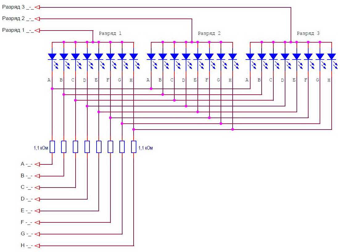
To connect three indicators, 11 pins were required, and not 24, as in the static control mode.
With dynamic indication, only one digit is lit at a time. A high-level signal (5 V) is applied to the common output of one of the bits, and low-level signals are sent to the segment outputs for those segments that should be lit in this bit. After a certain time, the next discharge is ignited. A high level is applied to its common output, and status signals for this bit are sent to the segment outputs. And so for all bits in an infinite loop. The cycle time is called the indicator refresh time. If the regeneration time is short enough, then the human eye will not notice the switching of discharges. It will seem that all discharges glow constantly. To avoid flickering of indicators, it is considered that the frequency of the regeneration cycle should be at least 70 Hz. I try to use at least 100Hz.
The dynamic indication circuit for LEDs with a common cathode looks like this.

The polarity of all signals is reversed. Now a low level is applied to the common wire of the active discharge, and a high level is applied to the segments that should glow.
Calculation of elements of dynamic indication of light-emitting diode (LED) indicators.
The calculation is somewhat more complicated than for the static mode. During the calculation, it is necessary to determine:
- average current of segments;
- impulse current segments;
- segment resistor resistance;
- pulsed current of the common conclusions of the discharges.
Because the indicator digits light up in turn, then the brightness of the glow determines the average current. We must choose it based on the parameters of the indicator and the required brightness. The average current will determine the brightness of the indicator at a level corresponding to static control with the same constant current.
Let's choose an average segment current of 1 mA.
Now let's calculate the impulse current of the segment. To provide the required average current, the pulsed current must be N times greater. Where N is the number of indicator digits.
I segm. imp. = I segm. avg. *N
For our scheme I segm. imp. = 1 * 3 = 3 mA.
We calculate the resistance of the resistors that limit the current.
R \u003d (U power - U segment) / I segment. imp.
R \u003d (5 - 1.5) / 0.003 \u003d 1166 ohms
We determine the pulse currents of the common conclusions of the discharges. At the same time, 8 segments can glow, which means that the pulse current of one segment must be multiplied by 8.
I category imp. = I segm. imp. * eight
For our scheme I discharge imp. = 3 * 8 = 24 mA.
- the resistance of the resistors is selected 1.1 kOhm;
- the outputs of the segment control microcontroller must provide a current of at least 3 mA;
- the outputs of the microcontroller for selecting the indicator digit must provide a current of at least 24 mA.
With such current values, the indicator can be connected directly to the terminals of the Arduino board, without the use of additional keys. For bright indicators, such currents are quite enough.
Schemes with additional keys.
If the indicators require more current, then additional switches must be used, especially for digit selection signals. The total discharge current is 8 times the current of one segment.
Wiring diagram for an LED indicator with a common anode in multiplexed mode with transistor switches for selecting digits.
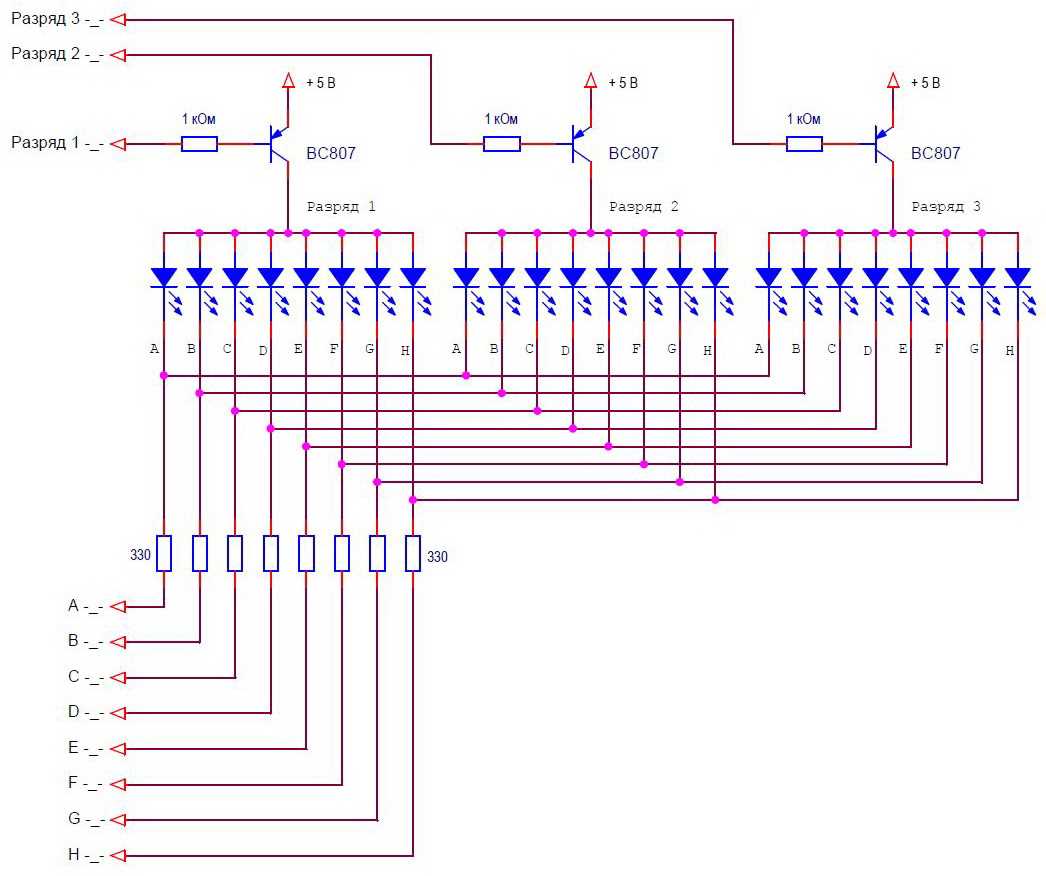
To select a bit in this circuit, it is necessary to generate a low level signal. The corresponding key will open and supply power to the indicator discharge.
Wiring diagram for an LED indicator with a common cathode in multiplexed mode with transistor switches for selecting digits.

To select a bit in this circuit, it is necessary to generate a high level signal. The corresponding switch will open and close the common output of the discharge to ground.
There may be circuits in which it is necessary to use transistor switches for both segments and common discharge leads. Such schemes are easily synthesized from the two previous ones. All circuits shown are used when the indicator is powered by a voltage equal to that of the microcontroller.
Keys for indicators with increased supply voltage.
There are indicators of large sizes, in which each segment consists of several LEDs connected in series. To power such indicators, a source with a voltage greater than 5 V is required. The switches must provide high voltage switching controlled by microcontroller level signals (usually 5 V).
The circuit of the keys that close the indicator signals to the ground remains unchanged. And the power keys should be built according to a different scheme, for example, this one.

In this scheme, the active discharge is selected by the high level of the control signal.
Between the switching of the indicator bits for a short time (1-5 µs), all segments should turn off. This time is necessary to complete the transient processes of switching keys.
Structurally, the conclusions of the discharges can be combined as in one case of a multi-digit indicator, or a multi-digit indicator can be assembled from separate single-digit ones. Moreover, you can assemble an indicator from individual LEDs combined into segments. This is usually done when it is necessary to assemble an indicator of very large dimensions. All the above schemes will be valid for such options.
In the next lesson, we will connect a seven-segment LED indicator to the Arduino board, write a library to control it.
Category: . You can bookmark.Sometimes it is required to connect several seven-segment indicators or an LED matrix to the microcontroller, while dynamic indication is used to display information. The essence of dynamic indication is the successive display of information on the indicators. The diagram below shows an example of connecting several seven-segment indicators (for example, with a common cathode) to implement a dynamic indication, in general, taking into account the point, 8 segments are obtained, but in the old fashioned way they are called that way. All conclusions (anodes) of the segments of the same name are connected together, for a total of 8 lines that are connected to the microcontroller through resistors. The common cathode of each indicator is connected to the microcontroller through a transistor. 
The indication algorithm is as follows: first, we set the required logic levels on the lines, depending on which segments need to be turned on on the first indicator (indication from left to right), with a high logic level to turn on, low to turn off the segment. Next, we apply a high logic level to the base of the transistor VT1, thereby the common cathode of the first indicator is connected to the common wire, at this moment those segments light up, on the anodes of which there is a logical unit. After a certain time (pause), the indicator is turned off by applying a low logic level to the base of the transistor, then again we change the logic levels on the lines in accordance with the output information intended for the second indicator, and apply a turn-on signal to the transistor VT2. Thus, in order in a circular cycle, we switch all the indicators, that's the whole dynamic indication.
To get a solid image without flickering, switching must be done at a high speed, to eliminate the flickering of the LEDs, the refresh rate must be set from 70 Hz or more, I usually set it to 100 Hz. For the above construction, the pause is calculated as follows: for a frequency of 100 Hz, the period is 10 ms, there are only 4 indicators, respectively, the glow time of each indicator is set at 10/4 = 2.5 ms. There are multi-digit seven-segment indicators in one housing, in which the segments of the same name are connected inside the housing itself, of course, to use them, it is necessary to use dynamic indication.
To implement dynamic indication, it is necessary to use interrupts on overflow of one of the timers. Below is the code using the TMR0 timer:
;Implementation of dynamic indication for 4 seven-segment indicators ;;;;;;;;;;;;;;;;;;;;;;;;;;;;;;;;;;;;; ; swapf STATUS,W ; clrf STATUS ; movwf STATUS_TEMP ; ; bcf ind1 ;turn off the 1st indicator bcf ind2 ;turn off the 2nd indicator bcf ind3 ;turn off the 3rd indicator bcf ind4 ;turn off the 4th indicator; incf shet,F ;increment register shet movlw .5 ;check register contents shet xorwf shet,W ;check if it is equal to 5 btfss STATUS,Z ; goto met1 ;number in shet register is not equal to 5 movlw .1 ;number in shet register is equal to 5: write number 1 movwf shet ;into shet register ; met1 movlw .1 ; check register contents shet xorwf shet,W ; equal to number 1 btfss STATUS,Z ; goto met2 ;number in shet register is not equal to 1: jump to met2 movf datind1,W ;number in shet register is equal to 1: copy movwf PORTB ;contents of datind1 register to PORTB register bsf ind1 ;turn on the 1st indicator of met2 movlw .2 ;check contents of register shet xorwf shet,W ; equal to 2 btfss STATUS,Z ; goto met3 ;number in shet register not equal to 2: jump to met3 movf datind2,W ;number in shet register is 2: copy movwf PORTB ;contents of datind2 register to PORTB register bsf ind2 ;turn on 2nd indicator goto exxit ;jump to label exxit met3 movlw .3 ;check register contents shet xorwf shet,W ;check for 3 btfss STATUS,Z ; goto met4 ;number in shet register not equal to 3: jump to met4 movf datind3,W ;number in shet register is 3: copy movwf PORTB ;contents of datind3 register to PORTB register bsf ind3 ;turn on 3rd indicator goto exxit ;jump to label exxit met4 movf datind4,W ;copy the contents of the datind3 register movwf PORTB ;to the PORTB register bsf ind4 ;turn on the 4th indicator; movlw .100 ;write 156 to timer register TMR0 movwf TMR0 ; ; movwf STATUS ; swapf W_TEMP,F ; swapf W_TEMP,W ; ; ;;;;;;;;;;;;;;;;;;;;;;;;;;;;;;;;;;;;;;;;;;;;;;;; ;;;;;;;;;;;;;;;;;;;;;;;;;;;;;;;;;;;;;; ; Main program ................. movlw b"11010011" ; OPTION_REG, thereby setting the internal ; setting the prescaler ratio 1:16 ; clrf shet ; reset register shet, before starting; interrupts on overflow TMR0, performed; clrf datind1 ;clearing registers for outputting information to clrf datind2 ;indicators, it is equivalent to turning off clrf datind3 ;indicators, as indicators with a common clrf datind4 ;cathode; bcf INTCON,T0IF ; clear TMR0 overflow interrupt flag bsf INTCON,T0IE ; enable TMR0 overflow interrupts bsf INTCON,GIE ; enable global interrupts; movlw b"00000110" ; 13.52 output example movwf datind1 ; movlw b"11001111" ; movwf dated2 ; movlw b"01101101" ; movwf dated3 ; movlwb"01011011" ; movwf dated4 ; ; . ................; .................; .................; ; end ; end of the whole program;
;;;;;;;;;;;;;;;;;;;;;;;;;;;;;;;;;;;;;;;;;;;;;;;;;;;;;;;;;;;;;;;;;;;;;;;;;;;;;;;;;;;;;;;;;; ;Implementation of dynamic indication for 4 seven-segment indicators ;Example clock frequency 4 MHz, machine cycle 1 µs org 0000h ;start program execution at address 0000h goto Start ;go to label Start ;;;;;;;;;;;;;;;;;;;;;;;;;;;;;;;;;;;;;;;;;;;;;;;;;;;;;;;;;;;;;;;;;;;;;;;;;;;;;;;;;;;;;;;;;; ;Interrupt routine org 0004h ;start subroutine execution at address 0004h movwf W_TEMP ;save key register values swapf STATUS,W ; movwf STATUS_TEMP ; bcf ind1 ;turn off the 1st indicator bcf ind2 ;turn off the 2nd indicator bcf ind3 ;turn off the 3rd indicator bcf ind4 ;turn off the 4th indicator incf shet,F ;increment register shet movlw .5 ; check the contents of register shet xorwf shet,W ; equal to 5 btfss STATUS,Z ; goto met1 ;number in register shet is not equal to 5 movlw .1 ;number in shet register is 5: write number 1 movwf shet ;to register shet met1 movlw .1 ; check contents of shet register xorwf shet,W ; equal to number 1 btfss STATUS,Z ; goto met2 ;number in shet register not equal to 1: jump to met2 movf datind1,W ;number in shet register is 1: copy movwf PORTB ; contents of datind1 register to PORTB register bsf ind1 ;turn on the 1st indicator goto exxit ;go to label exxit met2 movlw .2 ; check contents of shet register xorwf shet,W ; equal to number 2 btfss STATUS,Z ; goto met3 ;number in shet register not equal to 2: jump to met3 movf datind2,W ;number in shet register is 2: copy movwf PORTB ; contents of datind2 register to PORTB register bsf ind2 ;turn on the 2nd indicator goto exxit ;go to label exxit met3 movlw .3 ; check contents of shet register xorwf shet,W ; equal to number 3 btfss STATUS,Z ; goto met4 ;number in shet register not equal to 3: jump to met4 movf datind3,W ;number in shet register is 3: copy movwf PORTB ; contents of datind3 register to PORTB register bsf ind3 ;turn on the 3rd indicator goto exxit ;go to label exxit met4 movf datind4,W ; copy contents of datind3 register movwf PORTB ;to PORTB register bsf ind4 ;turn on the 4th indicator exxit bcf INTCON,T0IF ;reset TMR0 overflow interrupt flag movlw .100 ;write number 156 to timer register TMR0 swapf STATUS_TEMP,W ; restore contents of key registers swapf W_TEMP,F ; swapf W_TEMP,W ; retfie ;exit interrupt routine ;;;;;;;;;;;;;;;;;;;;;;;;;;;;;;;;;;;;;;;;;;;;;;;;;;;;;;;;;;;;;;;;;;;;;;;;;;;;;;;;;;;;;;;;;; ;Main program Start ................. ; initial setup registers ................. ;special purpose ................. bsf STATUS,RP0 ;write binary number 11010011 to register movlw b"11010011" ;OPTION_REG, thereby setting the internal movwf OPTION_REG ; clock source for TMR0 bcf STATUS,RP0 ;enable prescaler before TMR0 ;Set the prescaler ratio to 1:16 clrf shet ; reset the shet register before starting ;overflow interrupt TMR0, performed ;once after power on clrf datind1 ; clear registers for outputting information to clrf datind2 ;indicators, equivalent to off clrf datind3 ;indicators, since indicators with a common clrf datind4 ;cathode bcf INTCON,T0IF ;reset TMR0 overflow interrupt flag bsf INTCON,T0IE ;enable TMR0 overflow interrupts bsf INTCON,GIE ; enable global interrupts movlw b"00000110" ; 13.52 output example movlw b"11001111" ; movlw b"01101101" ; movlwb"01011011" ; ................. ; ................. ; ................. ; end ; end of the whole program |
In the main program, we first set up a timer using the OPTION_REG register, earlier I talked about using timers for . Next, we clear the shet register, intended for entering a count from 1 to 4, for each indicator. This register is incremented in the interrupt routine and adjusted there (it will count from 1 to 4), so this cleaning performed once after power on. Based on this register, we will determine which indicator to include and issue data corresponding to it. The next step is to clear the information storage registers, the four dataind1,2,3,4 registers corresponding to the four indicators. Clearing is equivalent to turning off the indicators, since in the interrupt service routine, the contents of these registers are transferred to the PORTB register, to which the indicator anodes are connected. This is necessary so that any garbage is not displayed on the indicators after interrupts are enabled, in principle this can not be done if the correct information is immediately written for output. Next, reset the timer overflow interrupt flag, enable TMR0 overflow interrupts, and finally enable global interrupts.
In the interrupt routine, we first turn off all the indicators (by applying low logic levels to the bases of the transistors), because it is not known which one is on. We increment the shet register, checking for equality to the number 5, if there is such a match, write the number 1 to the register, since it is necessary to keep count from 1 to 4. Next, we check which number is in the shet register, by which we load data from PORTB into PORTB information storage registers (dataind) for the corresponding indicator and turn it on. After that, we reset the TMR0 overflow interrupt flag, write the number 100 into the timer (the calculation of this value is given below), for a time delay, and exit the interrupt handler. At the first interruption, the first indicator turns on, at the second interruption, the second one, and so on in a circular cycle. In the main program, it remains only to load data into the information storage registers for each indicator. In the interrupt subroutine, do not forget to save and restore the values of key registers, I wrote about this in an article about.
To output numbers, it is better to use a character generator in the form of a data table. For example, to display the number 3456 on the indicators, it must be divided into digits, while it is better to use separate registers to store the numbers of digits (from 0 to 9), then run these registers through the character generator, thereby obtaining the correct bytes (loaded into the dataind registers) to ignite the respective segments.
We will take the frequency of the clock generator as 4 MHz, the machine cycle is 1 μs. Let the refresh rate of each indicator be 100 Hz (period T = 10 ms), respectively, the required time delay is 10/4 = 2.5 ms. The prescaler factor for TMR0 is set to 1:16, while the maximum possible delay is 256x16 = 4096 µs, and we need a pause of 2.5 ms. Let's calculate the number to write to TMR0: 256-((256x2.5)/4.096) = 256-156.25 = 99.75. After rounding, we get the number 100.
Below you can download a model for the Proteus program, firmware and source code with the implementation of dynamic indication on a 4-digit indicator with a common cathode using the PIC16F628A microcontroller. For example, the numbers 0000 are displayed on the indicator; 0001; 0002; 13.52; 9764.
Now consider connecting a matrix with a resolution of 8x8 pixels (LEDs). The structure of a matrix is usually considered in terms of rows and columns. In the picture below, in each column, the cathodes of all LEDs are connected, and in each row, the anodes. Strings (8 lines, LED anodes) are connected through resistors to the microcontroller. Each column (LED cathodes) is connected to the microcontroller through 8 transistors. The indication algorithm is the same, first we set the necessary logical levels on the rows, in accordance with which LEDs should light up in the column, then we connect the first column (indication from left to right). After a certain pause, we turn off the column, and change the logical levels on the lines to display the second column, then we connect the second column. And so alternately commute all the columns. Below is a diagram of connecting the matrix to the microcontroller. 
In total, to connect such a matrix, 16 microcontroller pins are required, which is quite a lot, therefore, to reduce the control lines, it is better to use serial shift registers.
The most common serial register is the 74HC595 microcircuit, which contains a shift register for loading data, and a hold register through which data is transferred to the output lines. Loading data into it is simple, set the logical 0 at the SH_CP clock input, then set the required logic level at the DS data input, after which we switch the clock input to 1, while the level value (at the DS input) is stored inside the shift register. At the same time, the data is shifted by one bit. We reset the SH_CP output to 0 again, set the required level at the DS input and raise SH_CP to 1. After the shift register is fully loaded (8 bits), we set the ST_CP output to 1, at this moment the data is transferred to the storage register and fed to the output lines Q0 ... Q7, after which we reset the output of ST_CP. During sequential loading, the data is shifted from Q0 to Q7. Pin Q7' is connected to the last bit of the shift register, this pin can be connected to the input of the second microcircuit, so you can load data into two or more microcircuits at once. The OE pin switches the output lines to the third (high-resistance) state when a logic 1 is applied to it. The MR pin is designed to reset the shift register, that is, setting low logic levels at the outputs of the register triggers, which is equivalent to loading eight zeros. Below is a diagram of loading data into the 74NS595 chip, setting the value 11010001 on the output lines Q0 ... Q7, provided that there were zeros initially: 
Consider connecting an 8×8 matrix to a PIC16F628A microcontroller using two 74HC595 shift registers, the diagram is shown below: 
The data is loaded into the DD2 chip (logic level control on the rows, LED anodes), then it is transferred through the Q7 pin to DD3 (column control), respectively, first we load the byte to enable the column, then the byte with the logical levels on the rows. Transistors switching matrix columns (LED cathodes) are connected to the output lines of DD3. Below is the program code for displaying an image on a matrix:
;;;;;;;;;;;;;;;;;;;;;;;;;;;;;;;;;;;;;;;;;;;;;;;; ;;;;;;;;;;;;;;;;;;;;;;;;;;;;;;;;;;;;;; ;Implementation of dynamic indication for a matrix with a resolution of 8x8 ;The frequency of the clock generator for the example is 4 MHz, the machine cycle is 1 μs org 0000h ;start program execution from address 0000h goto Start ;jump to the label Start ;;;;;;;;;;;;; ;;;;;;;;;;;;;;;;;;;;;;;;;;;;;;;;;;;;;;;;;;;;;;;; ;;;;;;;;;;;;;;;;;;;;;;;;;;;; ;Interrupt routine org 0004h ;start subroutine execution from address 0004h movwf W_TEMP ;save key register values swapf STATUS,W ; clrf STATUS ; movwf STATUS_TEMP ; ; movwf FSR_osn ;to the FSR_osn register movf FSR_prer,W ;restoring the previously saved value movwf FSR ;of the FSR register from the FSR_prer register ;;;;;;;;;;;;;;;;;;;;;;;;;;;;;;;;;;;;;;;;;;; ;;;;;;;;;;;;;;;;;;;;;; ;load the contents of the stolb register into the chip movf stolb,W ;copy the contents of the stolb register movwf var ;to the register var met2 btfsc var,0 ;set the output ds in accordance with btfss var,0 ; bcf ds ; bcf sh_cp ; rrf var,F ;Shift register var right to prepare;next bit goto met2 ;scetbit not equal to zero: jump to label met2 ;;;;;;;;;;;;;;;;;;;;;;; ;;;;;;;;;;;;;;;;;;;;;;;;;; ;load the contents of the INDF register into the chip; 74HC595 (serial shift register) movf INDF,W ;copy the contents of the INDF register movwf var ;to the var register movlw .8 ;write the number 8 into the scetbit register, for counting movwf scetbit ;transferred bits met1 btfsc var ,7 ;set output ds according to bsf ds ;value of 7th bit of register var btfss var,7 ; bcf ds ; bsf sh_cp ;clock sh_cp output to latch data bcf sh_cp ; rlf var,F ;Shift register var left to prepare;next bit decfsz scetbit,F ;Decrement with register condition scetbit goto met1 ;scetbit not equal to zero: jump to label met1 ; bsf st_cp ; clock the output st_cp to transfer the loaded bcf st_cp ; bytes to the output lines of the 74HC595 chips ; bcf STATUS,C ;reset the C bit of register status before shift rrf stolb,F ;left shift register stolb ; incf FSR,F ;Increment FSR register, prepare next ;Register to send data to 74HC595 decfsz shet,F ;Decrement with register condition shet goto exxit ;Shet register not equal to 0: Jump to exxit movlw data1 ;Shet register equal to 0: Write address first movwf FSR ;Register for storing information in the FSR register movlw .8 ;Writing the number 8 in the shet register, for maintaining movwf shet ;Counting columns ; exxit bcf INTCON,T0IF ;reset overflow interrupt flag TMR0 movlw . 124 ;write number 124 to timer register TMR0 movwf TMR0 ; ; movf FSR,W ;Save current FSR value movwf FSR_prer ;To FSR_prer movf FSR_osn ,W ;Restore previously saved value movwf FSR ;FSR from FSR_osn ; swapf STATUS_TEMP,W ; restore contents of key registers movwf STATUS ; swapf W_TEMP,F ; swapf W_TEMP,W ; ; retfie ;exit from interrupt subroutine;;;;;;;;;;;;;;;;;;;;;;;;;;;;;;;;;;;;;;;;;; ;;;;;;;;;;;;;;;;;;;;;;;;;;;;;;;;;;;;;;;;;;;; ;Main program Start ................ ;Initial setting of registers ................. ;Special purpose..... ............ bsf STATUS,RP0 ;write binary number 11010011 into register movlw b"11010010" ;OPTION_REG, thereby setting the internal movwf OPTION_REG ;clock source for TMR0 bcf STATUS,RP0 ;enable prescaler before TMR0; set the prescaler ratio 1:8; movlw .8 ;write 8 to shet register, before triggering movwf shet ;TMR0 overflow interrupts, executed;once, after power up movlw b"10000000" ;write binary number 10000000 to movwf stolb ;stolb register, to enable 1st column; is performed once, after turning on the power; movlw data1 ;write the address of the first register (storage registers movwf FSR_prer ;information) in the register FSR_prer, performed;one time after power on; movlw .8 ;clearing 8 registers of information output to movwf tmp ;matrix, equivalent to turning off movlw data1 ;matrix movwf FSR ; met3 clrf INDF ; incf FSR,F ; decfsz tmp,F ; goto met3 ; ; bcf INTCON,T0IF ; clear TMR0 overflow interrupt flag bsf INTCON,T0IE ; enable TMR0 overflow interrupts bsf INTCON,GIE ; enable global interrupts; m1 movlw data1 ; R output example movwf FSR ; movlw b"00000000" ; movwf INDF ; incf FSR,F ; movlw b"01111111" ; movwf INDF ; incf FSR,F ; movlwb"00001001" ; movwf INDF ; incf FSR,F ; movlwb"00011001" ; movwf INDF ; incf FSR,F ; movlwb"00101001" ; movwf INDF ; incf FSR,F ; movlw b"01000110" ; movwf INDF ; incf FSR,F ; movlw b"00000000" ; movwf INDF ; incf FSR,F ; movlw b"00000000" ; movwf INDF ; ; .................; .................; .................; ; end ; end of the whole program;
;;;;;;;;;;;;;;;;;;;;;;;;;;;;;;;;;;;;;;;;;;;;;;;;;;;;;;;;;;;;;;;;;;;;;;;;;;;;;;;;;;;;;;;;;; ;Implementation of dynamic indication for a matrix with a resolution of 8x8 ;Example clock frequency 4 MHz, machine cycle 1 µs org 0000h ;start program execution at address 0000h goto Start ;go to label Start ;;;;;;;;;;;;;;;;;;;;;;;;;;;;;;;;;;;;;;;;;;;;;;;;;;;;;;;;;;;;;;;;;;;;;;;;;;;;;;;;;;;;;;;;;; ;Interrupt routine org 0004h ;start subroutine execution at address 0004h movwf W_TEMP ;save key register values swapf STATUS,W ; movwf STATUS_TEMP ; movf FSR,W ;save the current value of the FSR register movwf FSR_osn ;to FSR_osn register movf FSR_prer,W ; restore previously saved value movwf FSR ;FSR from FSR_prer ;;;;;;;;;;;;;;;;;;;;;;;;;;;;;;;;;;;;;;;;;;;;;;;;; ;74HC595 (serial shift register) movf stolb,W ; copy contents of stolb register movwf var ;to register var movlw .8 ;write number 8 into scetbit register, for counting movwf scetbit ;transmitted bits met2 btfsc var,0 ;set ds output according to bsf ds ; 7th bit value of register var bsf sh_cp ;clock sh_cp output to latch data rrf var,F ; shift register var right to prepare ;next bit decfsz scetbit,F ;decrement with scetbit register condition goto met2 ;scetbit not equal to zero: jump to met2 label ;;;;;;;;;;;;;;;;;;;;;;;;;;;;;;;;;;;;;;;;;;;;;;;;; ;74HC595 (serial shift register) movf INDF,W ; copy contents of register INDF movwf var ;to register var movlw .8 ;write number 8 into scetbit register, for counting movwf scetbit ;transmitted bits met1 btfsc var,7 ;set ds output according to bsf ds ; 7th bit value of register var bsf sh_cp ;clock sh_cp output to latch data rlf var,F ;left shift var to prepare ;next bit decfsz scetbit,F ;decrement with scetbit register condition goto met1 ;scetbit not equal to zero: jump to label met1 bsf st_cp ;clock the output of st_cp to transfer loaded bcf st_cp ;bytes per 74HC595 output lines bcf STATUS,C ; clear C bit of status register before shift rrf stolb,F ;left shift register stolb incf FSR,F ;increment FSR register, prepare next ; register to send data to 74HC595 decfsz shet,F ;decrement with register condition shet goto exxit ;shet register not equal to 0: jump to exxit movlw data1 ;shet register is 0: write the address of the first movwf FSR ;Register to store information in FSR movlw .8 ;write number 8 into shet register, for reference movwf sheet ;column counts movlw b"10000000" ;write binary number 10000000 into movwf stolb ;register stolb, to include the 1st column exxit bcf INTCON,T0IF ;reset TMR0 overflow interrupt flag movlw .124 ;write number 124 to timer register TMR0 movf FSR,W ;save the current value of the FSR register movwf FSR_prer ;to FSR_prer register movf FSR_osn ,W ; restore previously saved value movwf FSR ;FSR from FSR_osn swapf STATUS_TEMP,W ; restore contents of key registers swapf W_TEMP,F ; swapf W_TEMP,W ; retfie ;exit interrupt routine ;;;;;;;;;;;;;;;;;;;;;;;;;;;;;;;;;;;;;;;;;;;;;;;;;;;;;;;;;;;;;;;;;;;;;;;;;;;;;;;;;;;;;;;;;; ;Main program Start ................. ;initial setting of registers ................. ;special purpose ................. bsf STATUS,RP0 ;write binary number 11010011 to register movlw b"11010010" ;OPTION_REG, thereby setting the internal movwf OPTION_REG ; clock source for TMR0 bcf STATUS,RP0 ;enable prescaler before TMR0 ;Set the prescaler ratio to 1:8 movlw .8 ;write number 8 into shet register before running movwf shet ; TMR0 overflow interrupts, running ;once after power on movlw b"10000000" ;write binary number 10000000 into movwf stolb ;register stolb, to include the 1st column Information with logical levels for the rows of each column is stored in 8 information storage registers, which are accessed through. The address of the first register is named data1. In addition to the initial writing of the shet and stolb registers, it is necessary to write the address of the first information storage register to the FSR_prer register (the register is data1, the entry in FSR_prer is performed once, then corrected in the handler), only after that, enable TMR0 overflow interrupts. Before enabling interrupts, it is desirable to clear the information storage registers, this operation is performed using the additional tmp register (as a counter) and indirect addressing, clearing is equivalent to turning off the matrix. In the interrupt handling routine, we load the contents of the stolb register into the DD2 chip (the first time you enter the handler after enabling interrupts, the register contains the number 10000000, as mentioned above). Loading starts from the low bit of the stolb register, which shifts in the direction from Q0 to Q7 (inside the DD2 chip) as it is loaded, the loading algorithm was discussed above, so I think it will not be difficult to understand the code. Next, we load the contents of the INDF register into DD2, this is one of the information storage registers, the address of which is in the FSR (the first time you enter the handler after enabling interrupts, the FSR contains the address of the first information storage register called data1). Loading starts from the high bit of the INDF register. After loading the considered 2 bytes, we clock the st_cp output, thereby the downloaded data is transmitted to the output lines of the DD2, DD3 microcircuits. Thus, at the first input to the handler, the first column of the matrix is switched, in which the LEDs light up, on the anodes of which there is a high logic level, in accordance with the contents of the data1 register (the first information storage register). Next, we shift the stolb register to the right by one bit in order to prepare the second column of the matrix for switching at the next entry into the interrupt handler. The C flag of the STATUS register must be cleared before the shift, since the shift occurs through this flag and its state is not known at the time of the shift. After the shift, we increment the FSR register, preparing the next storage register (after the data1 register) with logical row levels for the second column. Next, we decrement the shet register with the condition, and if it is not equal to zero, reset the TMR0 overflow interrupt flag, write the number to the timer, and exit the interrupt handler. The next time you enter the handler, the second column of the matrix will be enabled, and so on. When the shet register is reset (after switching the 8th column), the number 8 is written to it for the next cycle of switching columns, in addition, the value of the stolb register is corrected, the address of the first information storage register (data1) is written to the FSR register. Let's calculate the time delay for the TMR0 timer, the clock frequency is 4 MHz, the machine cycle is 1 µs. To avoid flickering of the LEDs, let's take the refresh rate of each column as 100Hz (period T=10ms), the time delay is 10/8 = 1.25ms. We set the prescaler ratio TMR0 to 1:8, while the maximum possible delay is 256x8 = 2048 µs. For a pause of 1.25 ms, the timer should count (256x1.25) / 2.048 = 156.25 times, rounding up we get 156 counts. Accordingly, it is necessary to write the number 256-156 = 100 into the timer. But this is not quite the correct value, since it takes some time to execute the interrupt routine, in this case it takes about 190 µs, recalculated taking into account the prescaler coefficient, we get 190/8 = 23.75 or 24 counts. The correct value to write to TMR0 is: 100+24=124. In the main program, we write 8 information storage registers, in accordance with what we want to display on the matrix. Below is a diagram explaining the output of information to the matrix for the above code. Below the link you can download the firmware and source code for the PIC16F628A microcontroller, with the implementation of dynamic indication on an 8x8 matrix using two 74HC595 shift registers, the connection diagram was discussed above. The letters R, L, the number 46, a smiley, and just a pattern in the form of a cross are alternately displayed on the matrix, this animation is shown in the video below. |

Dynamic indication is one of the problems that novice microcontroller programmers face. A lot has been said about it, but I decided to reinforce what is known with pictures and examples of C source texts, so that it would be easier to master this display method.
1 Fundamentals of the basics, or introduction
First of all, let's define the terminology that we will use throughout the article.
If you want to control a display consisting of a single seven-segment character, this does not cause any problems - it can be represented as 8 independent LEDs. If you need to display more information than a single character, problems begin: 2 familiarity is 16 LEDs, three - 24, etc., that is, for a three-digit display, the microcontroller outputs may simply not be enough, not to mention 6 or more bits displays and, especially, matrix indicators.
For simplicity, we agree that all our indicators are with a common cathode. The solution to the problem is quite simple: connect the outputs of the segments of all indicators to each other. Now, if you want to display information in the first familiarity, you should apply the required levels to the segment lines, and connect the common output of the first indicator to the common wire of the circuit. Of course, high levels must be present on the common cathodes of all other indicators. Obviously, the desired segments of the first indicator will light up. For output to the second, third, etc. indicators should do the same, i.e. by applying a logical zero to one of the common cathodes, we select the current displayed bit, and the state of the segment lines determines the visible symbol.
In order for the entire display to be perceived as continuously lit, the digits must be switched quickly - more often than 25 times per second. As you can see, the levels of all conclusions (which, by the way, have become significantly less than with the usual approach) are continuously changing, i.e. have not static levels, but dynamic ones, hence the name of the display method - dynamic.

Image with dynamic display
2 Varieties of hardware implementation
2.1 Flat matrices
If we abstract from seven-segment indicators, then our display can be represented as a matrix of individual LEDs, the anodes of which are combined into rows of the matrix, and the cathodes into columns. Actually, that's exactly what it is.
Obviously, by applying the required levels to the rows and columns of our matrix, we can light up any elementary LED-segment (aka pixel - this is a more traditional term for matrix displays). Depending on how exactly we will change the levels on rows and columns, we can get several types of dynamic indication:
- by line;
- by columns;
- segment by segment (per pixel);
- in a mixed way.
We have considered the option by columns in the previous chapter. The option by rows differs from it only in that the rows and columns of our matrix are interchanged. The segment-by-segment method consists in the fact that at any time only one row and one column has the level necessary to light the LED. That is, at any time, only one LED of the entire matrix can be lit (unlike previous options when the entire row or entire column can be lit at the same time). This method resembles a TV scan, when the beam goes around the entire screen, illuminating in right places phosphor. The mixed version, as the name implies, is that simultaneously "active" levels can be present on several rows and columns at once.
The first two options are very easy to implement, and therefore are widely used. The third option is used less often, because. requires more high speeds updates of information on rows and columns, and the average current through the segment (i.e., the brightness of the segment) in this case is significantly lower than in others. The last mixed method is the least common, although it has a number of positive qualities. First of all, this method requires that stable current sources be used in the row and column circuits, otherwise the brightness of the luminous segments will inevitably depend on their total number. And the calculation of signal combinations on rows and columns is not very easy.
2.2 Multidimensional matrices
The examples we have considered assume the implementation monochrome display, i.e. consisting of single color LEDs. What if you want to get a multi-color display, for example, from RGB LEDs? There are two possible solutions.
The first is to simply increase the number of rows (or columns) of our matrix by treating each RGB LED as 3 independent individual LEDs. The big disadvantage of this approach is the 3x increase in the number of rows (or columns). On the simple example it is easy to see what this translates into in practice: with the help of two eight-bit protrusions of the microcontroller, we can have a monochrome matrix of 8x8 segments or a color 4x4. Agree that in the second case it is practically impossible to display anything intelligible ...
The second way is to move from a "flat" matrix of segments to a "multidimensional". If the signal of each line is passed through a 1x3 multiplexer, then we can represent the display system of RGB LEDs as 3 independent matrices of the initial dimension: each matrix consists of LEDs of the same color, and we select the desired matrix with the multiplexer control signals. The figure explains what has been said.
Obviously, in the case of a multidimensional matrix, an additional number of control lines is also required, however, this number is not so large: on the same two controller ports, we can get a 7x7 color display !!!
2.3 Ways to reduce the dimension of matrices
If the number of microcontroller pins is very limited, we will have to look for ways to reduce the number of rows and columns of our matrix. Of course, miracles do not happen, and in this case we will have to pay by the fact that, in addition to the microcontroller, additional microcircuits will be used. As you may have guessed, here you can use the previously considered method of “multidimensional” matrices - after all, no one will forbid us to simply use a triple number of single-color LEDs instead of RGB LEDs? The main thing is to arrange them appropriately...
So, we can reduce the dimension of the matrix by applying:
- decoders or multiplexers;
- shift registers.
We have already met with multiplexers earlier, decoder, as you can guess, differs from the multiplexer unprincipally. It should only be added that using decoders / multiplexers for both rows and columns, it is possible to achieve a reduction in the matrix dimension in both dimensions at once, however, in this case, it may be necessary to use only segment-by-segment dynamic indication, with all its shortcomings.
Shift registers can help much better than decoders. Consider the diagram in the figure below.
It is easy to see that any number of rows and columns will only require an increase in the number of registers, and the number of microcontroller control lines involved will remain the same! A small minus this approach is that as the number of registers in the chain grows, it will be necessary to increase the speed of sequential output of information in them, which is not always easily achievable. So, for example, common microcontrollers of the family AVR, practically do not allow you to surpass the serial output speed of 10 megabits / sec. On the other hand, if you use other controllers that can output signals faster, problems of a different order may begin: the propagation of a high-frequency clock signal along a long line (and when large numbers registers, it will inevitably be so) is completely different from low-frequency, so special measures will be required when wiring printed circuit board and other things that we will not consider in this article.

3 Ways of software implementation
We will not consider the software implementation of all the mentioned options for dynamic indication - this will unreasonably inflate the article. We will limit ourselves to only three of the most "running" examples: a flat matrix with direct control of rows and columns, the same with the use of a decoder, and, finally, a variant with the use of shift registers. In all cases, special attention will be paid to all the nuances software implementation, that is, the C code will be accompanied by explanations only in cases where this coincides with the intention of the author, and by no means with your level of training. By this I hint that you should know the basics of C without me.
For all examples, we will agree that our display is built on seven-segment indicators with a common cathode.
3.1 The simplest way
Obviously, in the program it would be most convenient to have an array, the contents of which would uniquely determine which segments in which familiarity areas of the display are lit - a kind of analogue of screen RAM.
Let us introduce the definition of the following constants:
#define SCR_SZ 6 /* number of display character spaces */ #define ROWS PORTB /* port of display "rows", i.e. segment management */ #define COLS PORTD /* port for managing "columns", i.e. common cathodes */
Now let's declare an array-screen:
unsigned char SCR;
To begin with, we will assume that each element of the array corresponds to the familiarity of the display, and each bit of this element corresponds to a certain segment of the indicator. Which bit corresponds to which segment - in this case, it doesn’t matter how it doesn’t matter how these bits are set in the bytes of our array, we’ll just assume for now that they are already there. Also, for simplicity, we will assume that the common cathodes are connected to the port pins COLS sequentially: the least significant bit is the rightmost indicator, then the second, then the third, and so on.
How to make this array "display" on the display? Let's write the following code:
< SCR_SZ; pos++){ ROWS = SCR; COLS = ~(1 << pos); }
Will it perform the required function? Yes. But it's bad.
First of all, note that we have no control over the rate at which the contents of rows and columns are updated. Second, note that by the time the new array element is output to ROWS on the lines COLS the old value is still present! Where it leads? Moreover, for some fraction of a second, segments of a neighboring familiarity will be displayed on the familiarity, i.e. some segments will be falsely highlighted.
You can avoid this effect like this: before updating the content ROWS, always cancel the familiarity that was the previous one. In order not to bother with the definition of the previous familiarity, you can extinguish everything at once. So our code looks like this:
unsigned char pos; while(1) for(pos = 0; pos< SCR_SZ; pos++){ COLS = 0xFF; ROWS = SCR; COLS = ~(1 << pos); delay(); }
We added a blanking of the entire display before updating the state of the segment lines (putting a high level on the common cathodes, we will turn off the indicator regardless of what is present on the anodes) and introduced a delay at the end of the cycle. Now the display will work much better. But have we written a good program? Unfortunately no.
The fact is that the endless display cycle while just won't let us do anything else. What kind of program will we have, which only knows how to display something on the indicator ?! Of course, everything is not 100% bad, since something useful can be done on interrupts ... and instead of a delay delay() you can perform some actions ... But all this is very, very crooked: it is not desirable to perform something complex and cumbersome in interrupt handlers; on the other hand, if something complicated and cumbersome is done instead of a delay, then it is difficult to ensure the same computation time, otherwise it will turn out that the familiarity glows for a different period of time, which will visually look like their glow or flicker of different brightness.
In general, this option can be allowed only as an exception, only as a training example, or in the case (but five, only as an exception!), When the main problem to be solved is very simple (this can be, for example, the problem of measuring ADC voltage and display it).
What should be done? The answer, as always, is simple: all processes that should be executed imperceptibly from the solution of the main task (and the indication, of course, is such a process), should be performed by timer interrupts.
Interruptions will come at strictly defined intervals, which will ensure the uniformity of the glow of familiarity. Background indication will allow us to simply write something to the array at the right time in the main loop SCR- and it will instantly appear on the display! And all code changes will come down to the fact that instead of loops we use the interrupt handler function:
ISR(TIMER0_OVF_vect)( static unsigned char pos = 0; COLS = 0xFF; ROWS = SCR; COLS = ~(1<< pos); if(++pos == SCR_SZ) pos = 0; }
A few comments.
variable pos, denoting the number of the current glowing familiarity, we make a local static variable so that it retains its value from interrupt to interrupt. At the end of the function, we ourselves (after all, we no longer have a cycle) increase the familiarity number until we reach the limit - in this case, we go back to the beginning.
In the main program, we will only need to initialize the ports and the timer (in this case - Timer 0) so that it overflows at the intervals we need, and allow interrupts. After that, you can not remember about the indication - it will work quietly and peacefully on its own. But how to determine the desired timer overflow interval? Very simple. The human eye perceives flicker with a frequency of more than 25 Hz as a continuous glow. We have 6 indicators, each of them should flicker with such a frequency, which means that the information on the display should be updated at a frequency of 25 x 6 = 150 Hz or more. Now let's calculate the value of the timer prescaler: divide the clock frequency of the MK by 256 ( Timer 0 everyone has AVR eight-bit, which means it overflows, counting up to 256) - this will be the desired value of the timer prescaler. Of course, it is unlikely that the result will match one of the standard prescaler values - this is not a problem, you can take the nearest smaller suitable value. The indication will work at a higher frequency, but this will not degrade its quality! A side effect will be a large load on the MK core for indication. If this greatly interferes with the main program, you will have to transfer the indication to another timer, for example, 16-bit Timer 1, or enter a counter to skip timer overflows:
#define SKIP 15 /* number of timer interrupts to skip */ ISR(TIMER0_OVF_vect)( static unsigned char pos = 0; static unsigned char skip = SKIP; if (--skip) return; skip = SKIP; COLS = 0xFF; ROWS = SCR ; COLS = ~(1<< pos); if(++pos == SCR_SZ) pos = 0; }
In these simplified examples, we assume that the port COLS, except for the common cathodes of the indicators, nothing else is connected. However, in real life, such happiness does not happen often, and something else is most likely connected to the remaining lines of this port. Therefore, when organizing dynamic indication, one should always ensure the invariance of the state of all port lines that are not directly involved in the indication. This is done simply: instead of simply writing a new value to the port, masking unnecessary bits should be used:
COLS |= 0x3F; // so we extinguish all familiarity COLS &= ~(1< Both statements do not change the value of the high bits of the port COLS. The decoder can be used either to convert HEX or BCD code into seven-segment characters, or to select one of the columns of the matrix. Both options will differ from the simplest method considered earlier only in how the output to the ports will be organized. ROWS and/or COLS to which the decoder inputs will be connected. ISR(TIMER0_OVF_vect)( static unsigned char pos = 0; COLS |= 0x3F; ROWS = (ROWS & 0xF0) | (SCR & 0x0F); COLS &= ~(1<< pos);
if(++pos == SCR_SZ) pos = 0;
}
As you can see, the changes are minimal - before being displayed in ROWS character code from array SCR, the high bits are masked, after which the low bits are set according to the character code. That is, we consider that the decoder is connected to the 4th least significant bits of the port ROWS. I hope it makes no sense to give an example for decoding columns - everything is clear anyway. Although dynamic indication using shift registers is not fundamentally different from the previously discussed methods, there are several options for its implementation. We will consider the simplest - the output of bits by purely software means. And in the implementation of others (using USI/USART/SPI/TWI) you can try your hand at yourself. For the variant of the previously selected display of 6 seven-segment character spaces, we use 2 shift registers of the type 74HC595. This register is controlled by three signals: serial data input clock CLK, the actual data DATA and pulse of simultaneous parallel output of information written to the register SET. Let's declare the corresponding macros (for simplicity, we will “bring” all signals to one port): #define CLK _BV(PB0) #define DATA _BV(PB1) #define SET _BV(PB2) #define REG_PORT PORTB To write to the register, it is convenient to write a separate function: Static void shift(unsigned char d)( unsigned char i; for (i=0; i< 8; i++){
// устанавливаем нужный уровень DATA
if(d & 1)
REG_PORT |= DATA;
else
REG_PORT &= ~DATA;
REG_PORT |= CLK; // даем импульс CLK
REG_PORT &= ~CLK;
d >>= 1;
}
}
It is highly desirable to make this function static, because it will be used in the interrupt handler. The compiler will most likely make static functions in the form inline-inserts in the interrupt handler, i.e. there will be no unnecessary use of the stack, which is not guaranteed for non-static functions. Now our interrupt handler will look like this: ISR(TIMER0_OVF_vect)( static unsigned char pos = 0; shift(SCR); shift(~(1<< pos));
REG_PORT |= SET; // выдаем импульс SET
REG_PORT &= ~SET;
if(++pos == SCR_SZ) pos = 0;
}
Since the data written to the registers appear at its outputs at the same time, there is no need to turn off the indicators first. It should be remembered that software serial output is a rather long process, especially for matrices of large dimensions, so you should optimize it as much as possible in terms of speed. This can best be done using the serial output hardware found in the MCU. So, you got acquainted with the basics of implementing dynamic indication. But, as usual, questions are not decreasing, but increasing. Anticipating some of them, I will try to immediately give the necessary answers. Everything that we have considered earlier referred to indicators with common cathodes. And if you want to use with common anodes? In general, everything remains the same, except that before the output it will be necessary to invert the data - the blanking of the familiarity is carried out by outputting zeros to COLS, ignition - respectively, units, and segments in ROWS will include zeros instead of ones. So the interrupt handler becomes something like this: ISR(TIMER0_OVF_vect)( static unsigned char pos = 0; COLS &= 0xC0; ROWS = ~SCR; COLS |= (1<< pos);
if(++pos == SCR_SZ) pos = 0;
}
Everything is simple. Unless, of course, you try to write a universal code that is suitable for both common anodes and common cathodes. This can be done in two ways: either using conditional compilation directives, or using a transform function. I will demonstrate the first option, and I suggest thinking about the second one on your own. #define COMMON_ANODE 1 ISR(TIMER0_OVF_vect)( static unsigned char pos = 0; #if COMMON_ANODE != 1 COLS &= 0xC0; ROWS = ~SCR; COLS |= (1<< pos);
#else
COLS |= 0x3F;
ROWS = SCR;
COLS &= ~(1 << pos);
#endif
if(++pos == SCR_SZ) pos = 0;
}
It's a bit cumbersome, but if you write it once, you can use it in all projects with almost no changes. In many cases, the display is used not only as a means of displaying information coming from inside the device, but also for displaying information entered by the user. And in this case, it is necessary to be able to somehow separate the unchanged from the changeable on the display. The easiest way to do this is to make the corresponding familiarity (or several familiarity) flicker. It is very easy to do this. Let's introduce a global variable, each single bit of which will denote a blinking familiarity: Now we modify the interrupt handler a little: ISR(TIMER0_OVF_vect)( static unsigned char pos = 0; static unsigned char entry = 0; COLS |= 0x3F; if(!(blink & (1< As you can see, only one static variable has been added - the counter of inputs to the interrupt handler entry, and a condition test operator. The logic is simple: the output of the next familiarity is carried out only if either in the corresponding bit blink zero, or the most significant bit of the counter entry equals 1. If, suppose, blink contains all zeros, then this condition is always satisfied - all familiarity are displayed. If blink contains 1 in one of its bits, then the corresponding character will be displayed only at the time when the most significant bit of the counter is 1. Since the counter is incremented each time the interrupt handler is entered, the corresponding character will flicker at a frequency 128 times less than interrupt frequency. I wrote about adjusting the brightness in a separate article, which was called that. Earlier it was said that the happiness to allocate the entire MK port for indication falls out quite rarely. But even less often it is lucky to get a convenient PCB trace if one port is used entirely for the rows, and the other port is used for the columns of the display matrix. Much more often, optimal routing is obtained only when rows and columns are mixed between two or even more ports of the microcontroller. You won't have to sacrifice the beauty of the printed circuit board if you organize software bit swapping during the indication. Let's consider some abstract example. Let the best tracing be provided with the following distribution of signals along the lines of the MC ports: Segment A Segment B segment H Segment C Segment D G segment Segment E Segment F As you can see, the matrix lines are mixed among the three ports, and all unused lines of these ports should, of course, not change their levels during the indication process. It is best to start developing a dynamic indication function for this case by distributing the segments over the symbol bits. Previously, we considered that in the array SCR we store bit masks of characters, i.e. units in a byte denote luminous segments. We did not think about which bit corresponds to which segment. So, now is the time to think about it. It is convenient to paint the purpose of the port lines in the form of three plates: 1
A
0
4
H
3
2
B
F
E
5
G
D
C
We must collect all segments into one byte. You will have to do this with shift operations, so you should try to distribute them so as to make a minimum of shifts. Let's discuss. If the segment bits FEGDC leave in the symbol so that they fall into PORTD without shifts, then the segment H can also remain in the 6th bit of the character, and it also does not have to be shifted before output PORTC, but for segments BUT and AT bits 7 and 3 will remain, that is, most likely a segment AT will have to be shifted by 3 positions before output, and the segment BUT- by 6. I will stop at this option, and you can continue searching for the minimum of shifts (shifts by several positions are not such a fast operation, so it is desirable to reduce their number to a minimum). So, in our case, we got the following distribution of bits by byte-character: A
H
F
E
B
G
D
C
Note the bit masks for output to the appropriate ports: D
0
0
1
1
0
1
1
1
0x37
B
1
0
0
0
0
0
0
0
0x80
C
0
1
0
0
1
0
0
0
0x48
With the help of these masks, using the “bitwise AND” operation, we select the necessary bits for output to the port. Let's declare mask constants: #define MASKD 0x37 #define MASKC 0x80 #define MASKC 0x48 Previously, we output a character to a single port ROWS, now this procedure is divided into three parts: PORTD = (PORTD & ~MASKD) | (SCR & MASKD); PORTB = (PORTB & ~MASKB) | ((SCR & MASKB) >> 6); PORTC = (PORTC & ~MASKC) | ((SCR & _BV(6)) | (((SCR & _BV(3)) >> 3); Please note that for output to PORTC one bit must be output without a shift, and the second - with a shift, so instead of MASKC had to use separate macros _BV(). Now it remains to decide how to extinguish and light the corresponding familiarity. Let's declare the constants corresponding to the familiarity control bits: #define COM0 _BV(0) #define COM1 _BV(3) #define COM2 _BV(4) #define COM3 _BV(5) #define COM4 _BV(7) #define COM5 _BV(3) #define COM_D (COM5) #define COM_C (COM2 | COM3 | COM4) #define COM_B (COM0 | COM1) To extinguish all familiarity, it is necessary to output the corresponding constants to the ports COM_x: PORTD |= COM_D; PORTC |= COM_C; PORTB |= COM_B; But to enable familiarity, you will have to be smart (it makes no sense to output to all three ports, because only one single bit will be active in a certain port, depending on the value pos), for example, using the operator switch: Switch(pos)( case 0: PORTB &= ~COM0; break; case 1: PORTB &= ~COM1; break; case 2: PORTC &= ~COM2; break; case 3: PORTC &= ~COM3; break; case 4: PORTC &= ~COM4; break; case 5: PORTD &= ~COM5; break; ) It's not the prettiest way, but it works. Thus, our interrupt handler takes the following form: ISR(TIMER0_OVF_vect)( static unsigned char pos = 0; static unsigned char entry = 0; // extinguish PORTD |= COM_D; PORTC |= COM_C; PORTB |= COM_B; // output PORTD = (PORTD & ~MASKD) | ( SCR & MASKD); PORTB = (PORTB & ~MASKB) | ((SCR & MASKB) >> 6); PORTC = (PORTC & ~MASKC) | ((SCR & _BV(6)) | (((SCR & _BV (3)) >> 3); // blink if(!(blink & (1<< pos)) || (++entry & 0x80)) {
switch(pos){
case 0: PORTB &= ~COM0; break;
case 1: PORTB &= ~COM1; break;
case 2: PORTC &= ~COM2; break;
case 3: PORTC &= ~COM3; break;
case 4: PORTC &= ~COM4; break;
case 5: PORTD &= ~COM5; break;
}
}
if(++pos == SCR_SZ) pos = 0;
}
Now it remains to figure out how to describe the symbols for output in a more convenient way ... I suggest doing the following: define constants corresponding to the bits of the segments, and then “construct” the necessary symbols from these constants: // elementary segments #define _A _BV(7) #define _B _BV(3) #define _C _BV(0) #define _D _BV(1) #define _E _BV(4) #define _F _BV(5) #define _G _BV (2) #define _H _BV(6) // digit symbols #define d_0 (_A | _B | _C | _D | _E | _F) #define d_1 (_B | _C) #define d_2 (_A | _B | _G | _D | _E) // and so on Thus, if you need to print a zero to the far right of the display, you just have to write in the right place: SCR = d_0; If in another project you need to distribute the bits differently, you will only change the numbers in the macros _BV() for elementary segments, and all characters will be "remade" automatically. For the simplest cases described at the beginning, you won’t have to do anything else at all, but for the “bit swapping” option, you will, of course, have to tinker. With the traditional shortage of MK outputs, the problem of a large number of buttons, without which rarely any device can do, is very acute. Various matrix inclusions, etc. are used. tricks, however, by slightly complicating the function of dynamic indication, it is easy to get at the disposal of as many buttons as there are familiarity in the display, while additionally you need to use only one port of the microcontroller. True, each button still has to be put on a diode. Schematically, this is shown in the figure. And programmatically it looks like this: #define keypin() (!(PIND & _BV(KEY))) ISR(TIMER0_OVF_vect)( static unsigned char pos = 0; static unsigned char entry = 0; static unsigned char tmp_key = 0; ROWS = 0; if(keypin( )) tmp_key |= 1<< pos;
COLS |= 0x3F;
if(!(blink & (1<< pos)) || (++entry &0x80)){
ROWS = (ROWS & 0xF0) | (SCR & 0x0F);
COLS &= ~(1 << pos);
}
if(++pos == SCR_SZ){
pos = 0;
key = tmp_key;
tmp_key = 0;
}
}
Here key- this is a macro that sets the bit of the selected port, on which all buttons are "connected", the macro keypin() returns the boolean value TRUE if the selected pin is logic low. In the example, the buttons are connected to PORTD. Each time a timer interrupt occurs, all segments are first extinguished - this is necessary so that the current through the LEDs does not lead to an erroneous non-detection of a pressed button. After that, the button input is polled - if there is a low level, then the button connected to the corresponding pos cathode is pressed. In a variable tmp_key button states are accumulated, which are rewritten into a global variable key after completion of the display cycle. You just need to analyze the value from time to time key and handle the detected presses: Static unsigned char get_key()( unsigned char tmp = 0; tmp = key; _delay_ms(10); if(key == tmp) return tmp; else return 0; ) This simple feature guarantees that there will be no button chatter, even though, due to the “dynamic” nature of button polling, the chance of chatter is already low. So, you have mastered quite typical techniques for implementing dynamic indication. I think this will be enough for you for the first time, and maybe even for the rest of your life. In the end, the main thing is an understanding of techniques and algorithms, and subtleties and nuances can always be added on your own. But what else can wait "near" the dynamic indication? As I said earlier, you can add, and up to independent regulation of each segment. You can think about the optimality of the interrupt handler - for educational purposes, I wrote rather rough code, for example, I used everywhere SCR, although it would be more optimal to read the value into a local variable once, and then operate with its value. Although the optimizer will certainly help out with my approach, for the sake of practice it is worth trying and optimizing yourself, controlling yourself by the size of the resulting code and / or the speed of the program. You can think about the interesting idea of automatically adjusting the brightness of the display depending on the level of ambient light. As you know, LED indicators are the worse distinguishable, the darker it is around - they just blur. Therefore, in the dark, it is reasonable to reduce the brightness of the indicators, increasing it in the daytime. The simplest thing is to use a separate photoresistor or LED as a light sensor, but you can do it differently: it is known that the LED can also work as a photodiode, so if you use the port connected to the input for indication ADC, then, if desired, you can measure the photo-emf of the non-luminous segment of the indicator, and use this value to adjust the brightness ... You can think about the use of hardware serial output, which I have already hinted at. An interesting version of a completely universal approach to dynamic indication, which I also recommend getting acquainted with, was suggested by MOLCHEC. Briefly, the essence: the distribution of segments by character bits, the assignment of ports for controlling the indicator, and even the indicator type - in short, all-all-all parameters - are set in the form of a configuration table in EEPROM. Programmatically, everything is organized on the basis of this table: from inversion depending on the type of indicator, to bit swapping on different ports. At the same time, the source code of the dynamic indication program always remains unchanged, and the configuration table is compiled by the end user, depending on their preferences. The method is indeed universal and flexible, however, it is associated with an increased consumption of program memory.3.2 Decoder method
Option to use a decoder to get a seven-segment character:3.3 Method with registers
4 For those who never have enough
4.1 Anodes, cathodes - what to choose?
4.2 Flicker
4.3 Adjusting the brightness of the segments
4.4 Arbitrary distribution of conclusions
4.5 Button support

5 What else?
| 3 Written by ARV, at 06:48 08/25/2010 Misha, if I were you, I would not give such peremptory statements “you can’t do it”, “no one wrote” or “copyrights”, because firstly, this is not polite, and secondly: 1. I made a running line on a 10x16 matrix a long time ago (what it was) - you can find a video of its work in this note http://site/content/view/160/38/ 2. I wrote an article (you will find it in the news - the last one for today) on how to make a ticker on the LCD. if you strain your brain a little, then redoing the algorithm for outputting to a matrix is a trifle. 3. there is not a single article on my site copied from somewhere (copy-paste is not a copyright, you have sealed it), all materials are completely original. many sites have copies of these materials with my permission (or the permission of the authors of the materials, who have every right to publish their materials at once in many places). |
Only registered users can leave comments.
Please register or login to your account.
Indicators are usually located in places convenient for viewing the information displayed on them. The rest of the digital circuit can be located on other printed circuit boards. With an increase in the number of indicators, the number of conductors between the indicator board and the digital board increases. This leads to certain inconveniences in the development of the design and operation of the equipment. The same reason leads to an increase in its value.
The number of connecting conductors can be reduced by making the indicators work in a pulsed mode. The human eye has inertia, and if the indicators are forced to display information alternately at a sufficiently high speed, then it will seem to a person that all indicators display their information continuously. As a result, it is possible to alternately transmit the displayed information on the same conductors. Usually a refresh rate of 50 Hz is sufficient, but it is better to increase this frequency to 100 Hz.
Let's look at the block diagram of the inclusion of seven-segment LED indicators, shown in Figure 1. This circuit can provide a dynamic indication of the output digital information.
Figure 1. Structural diagram of dynamic indication
The circuit shown in Figure 1 displays four digital digits. Each bit is briefly connected to its input of the switch. The generator is used to set the speed of updating information on the indicators. The binary counter sequentially generates four states of the circuit, and through the keys provides alternate power supply to the seven-segment indicators.
As a result, when the switch supplies a BCD code from input A to the inputs of a seven-segment decoder, this code is displayed on the HL1 indicator. When the switch supplies a BCD code from input B to the inputs of the seven-segment decoder, this code is displayed on the HL2 indicator, and so on, in a cycle.
The information update rate in the considered circuit will be four times less than the generator frequency. That is, in order to obtain an indicator flickering frequency of 100 Hz, an oscillator frequency of 400 Hz is required.
How many times have we reduced the number of connecting conductors as a result? It depends on where we draw the cross section of the circuit. If we leave only indicators on the display board, then their operation will require 7 information signals for the segments and four switching signals. There are 11 conductors in total. In a static indication circuit, we would need 7 × 4 = 28 conductors. As you can see, there is a win. When implementing an 8-bit display unit, the gain will be even greater.
An even greater gain will be if the cross section of the circuit is drawn along the inputs of the indicators. In this case, a four-digit display unit will require only six signal conductors and two circuit power conductors. However, such a cross-sectional point of the dynamic indication circuit is used very rarely.
Now let's calculate the current flowing through each segment of the LED when it is lit. To do this, we use the equivalent circuit of current flow through one of the segments of the indicator. This scheme is shown in Figure 2.

As mentioned earlier, an LED requires a current of 3 to 10 mA to function properly. Let's set the minimum current of the LED to 3 mA. However, in the pulse mode of operation, the brightness of the indicator glow decreases by N times, where the coefficient N is equal to the duty cycle of the current pulses supplied to this indicator.
If we are going to keep the same brightness of the glow, then we need to increase the value of the pulsed current flowing through the segment by N times. For an eight-digit indicator, the coefficient N is equal to eight. Suppose we initially chose a static current through the LED equal to 3 mA. Then, to maintain the same brightness of the LED in an eight-digit indicator, a pulsed current is required:
I seg din = I seg stat× N= 3mA×8 = 24mA.Only some series of digital microcircuits can hardly provide such a current. For most series of microcircuits, amplifiers made on transistor switches will be required.
Now let's determine the current that will flow through the key, switching power to individual bits of an eight-bit display unit. As can be seen from the circuit shown in Figure 2, the current of any segment of the indicator can flow through the key. When the number 8 is displayed, it will be necessary to light all seven segments of the indicator, which means that the pulse current flowing through the key at this moment can be determined as follows:
I cl \u003d I segdin× N seg= 24mA×7 = 168mA.How do you like this current?! In amateur radio circuits, I often come across solutions where the switching current is taken directly from the output of the decoder, which cannot deliver a current of more than 20 mA, and I ask myself the question - where can I see such an indicator? In total darkness? It turns out a "night vision device", that is, a device whose readings are visible only in complete darkness.
And now let's look at the schematic diagram of the resulting display unit. It is shown in Figure 3.

Figure 3. Schematic diagram of the dynamic indication block
Now, after we have received the dynamic indication circuit, we can discuss its advantages and disadvantages. The undoubted advantage of dynamic indication is a small number of connecting wires, which makes it indispensable in some cases, such as working with matrix indicators.
As a disadvantage, the presence of large pulsed currents should be cited, and since any conductor is an antenna, the dynamic indication serves as a powerful source of interference. Another route for interference is the power supply.
Note that the fronts of the switching pulses are very short, so their harmonic components cover the radio frequency range up to ultrashort waves.
So, the use of dynamic indication allows minimizing the number of connecting wires between the digital device and the indicator, but at the same time it is a powerful source of interference, so its use in radio receivers is undesirable.
If for some reason, for example, the need to use matrix indicators, you have to use dynamic indication, then you need to take all measures to suppress interference.
As measures to suppress interference from dynamic indication, shielding of the unit, connecting cable and boards can be mentioned. The use of the minimum length of connecting wires, the use of power filters. When shielding a block, it may be necessary to shield the indicators themselves. In this case, a metal mesh is usually used. This grid can simultaneously increase the contrast of the displayed characters.
Literature:
Together with the article "Dynamic indication" they read:
Indicators are designed to display various types of information for a person. The simplest kind of information is...
http://website/digital/Indic.php
Discharge indicators are used both to indicate bit information and to display decimal information. When constructing decimal indicators of the cathode...
http://website/digital/GazIndic/
Currently, LEDs are used almost everywhere to display binary information. This is due to...
http://website/digital/LED.php
Principles of operation of liquid crystal indicators ... Modes of operation of liquid crystal indicators ... Formation of a color image ...
http://website/digital/LCD.php
DIn order to display a multi-digit number on the indicator, you must first carry out a tricky manipulation with it, which consists in breaking the number into its components. As an example, I will give the display of the number 1234 on a quad seven-segment indicator with a common anode.
To display a four-digit number, you need to create one common variable in which the number you want to display will lie (variable W), four variables that will store data for each sign (N) and four more variables for intermediate transformations (M) so as not to touch the main variable. The variable must correspond to the value that will be stored in it.I. So for a variableWtype will sufficeinteger , since a variable of this type is capable of xpAnimate values from -32768 to +32767 (orword unless you plan to use negative numbers). In variablesNwill lie numbers from 0 to 9 so it will be sufficient to use a variable of typebyte . And in variablesM will bethe same values as in the variableW, so we set the type integer .
Dim W As Integer
Dim N1 As Byte
Dim N2 As Byte
Dim N3 As Byte
Dim N4 As Byte
Dim M1 As Integer
Dim M2 As Integer
Dim M3 As Integer
Dim M4 As Integer
After declaring variables, we set up ports for outputwhich will be used to connect the indicator:
DDRC = &B11111111
DDRD = &B11111111
DDRC=&B 00001111 and DDRD=&B 01111111 (four first legs of port Cfor anodes and six first ports D sub segments).
Then assign to a variable W the value that we are going to display on the indicator:
W=1234
"Arial","sans serif""> In the main loop of the program, we assign the variables M the value of the variableW , I do this:
M1=W
M2 = M1
M3 = M1
M4 = M1
"Arial","sans serif""> This is not paranoia)), this is done with the aim that in all variables M there is the same number, since during the assignment operation an interrupt (if there is one and not disabled) can easily break in, in the handler of which the variableW can change. And if the assignment went like this: М1= W , M 2= W , M 3= W , M 4= W in the variables M will lie different meanings which will lead to a mess in the readings.
After assignment variable values start working with
each of them, converting in such a way that into a variable N got the value that will be
displayed on the indicator: in a variable N 1 should be "1", in N 2 - "2", in N 3 - "3", and in N 4 - "4".
M1=M1/1000" M1=1234/1000=1.234
N1=Abs(m1)" N1=Abs(1.234)=1
abs – a function that returns an integer number of a variable. To a variable N 1 hit the unit, which was actually required.
To assign a two to a variable N 2 operation will be a bit more complicated:
M2= M2 Mod 1000 " M2 =1234 Mod 1000 = 234
M2=M2/100" M2=234/100=2.34
N2= Abs (m2) " N2 = Abs (2.34) = 2
"Arial","sans serif""> To start with the functionMod
we return the first three
digits of the number (the remainder of the division by 1000), and then everything is as in the first case.
With the last two digits, almost the same thing:
M3 = M3 Mod100
M3=M3/10
N3 = Abs (m3)
M4 = M4 Mod 10
N4= Abs (m4)
Now our variables contain the values \u200b\u200bthat we want to display, it's time for the microcontroller to kick its legs and display these values on the indicator, for this we call the display processing subroutine:
"Arial","sans serif"">
Gosub Led
"Arial","sans serif""> The processor will jump to the subroutine labeledLed:
Led:
Portc = &B00001000
"Arial","sans serif""> Here we serve a high level onPORTC .3, we have connected the anode of the first category to this leg. We then choose which segments to light to display the value of the first variable. She is one of us, so zero will be on her feet Portd .1 and Portd .2, which corresponds to the segments B and C indicator.
Select Case N1
End Select
Waitms 5
"Arial","sans serif""> After the necessary segments have been lit, we wait 5 ms and proceed to display the following numbers:
Portc = &B00000100
Select Case N2
Case 0 : Portd = &B11000000
Case 1 : Portd = &B11111001
Case 2 : Portd = &B10100100
Case 3 : Portd = &B10110000
Case 4 : Portd = &B10011001
Case 5 : Portd = &B10010010
Case 6 : Portd = &B10000010
Case 7 : Portd = &B11111000
Case 8 : Portd = &B10000000
Case 9 : Portd = &B10010000
End Select
Waitms 5
Portc = &B00000010
Select Case N3
Case 0 : Portd = &B11000000
Case 1 : Portd = &B11111001
Case 2 : Portd = &B10100100
Case 3 : Portd = &B10110000
Case 4 : Portd = &B10011001
Case 5 : Portd = &B10010010
Case 6 : Portd = &B10000010
Case 7 : Portd = &B11111000
Case 8 : Portd = &B10000000
Case 9 : Portd = &B10010000
End Select
Waitms 5
Portc = &B00000001
Select Case N4
Case 0 : Portd = &B11000000
Case 1 : Portd = &B11111001
Case 2 : Portd = &B10100100
Case 3 : Portd = &B10110000
Case 4 : Portd = &B10011001
Case 5 : Portd = &B10010010
Case 6 : Portd = &B10000010
Case 7 : Portd = &B11111000
Case 8 : Portd = &B10000000
Case 9 : Portd = &B10010000
End Select
Waitms 5
"Arial","sans serif""> After displaying information on the indicator, you must return to the main program loop, where you need to complete the loop and mark the end of the program.
"Arial","sans serif""> Here's what we get in the end:
 "Arial","sans serif"">
"Arial","sans serif""> Due to the small delay, the switching will not be visible to the human eye and we will see the integer 1234.
You can download the source code and the project in Proteus below:"Arial","sans serif"">