So, resistor... The basic element of building an electrical circuit.
The job of a resistor is current limiting flowing through the chain. NOT in the conversion of current into heat, namely in current limiting. That is, without resistor a big one flows through the chain current, embedded resistor the current has decreased. This is his work, performing which this element of the electrical circuit generates heat.
Light bulb example
Consider work resistor on the example of a light bulb in the diagram below. We have a power source, a light bulb, an ammeter that measures current passing through the chain. And Resistor. When resistor is absent in the circuit, a large current, for example, 0.75A. The light bulb burns brightly. A resistor was built into the circuit - the current had an insurmountable barrier flowing through the circuit current dropped to 0.2A. The light bulb is less bright. It is worth noting that the brightness with which the light bulb burns also depends on the voltage on it. The higher the voltage, the brighter.
In addition, on resistor going on voltage drop. The barrier not only delays current, but also "eats" part of the voltage applied by the power source to the circuit. Consider this fall in the figure below. We have a 12 volt power supply. Just in case, an ammeter, two voltmeters in reserve, a light bulb and resistor. Turn on the circuit without resistor(left). The voltage at the bulb is 12 volts. We connect the resistor- part of the voltage fell on it. The voltmeter (bottom right in the diagram) shows 5V. The remaining 12V-5V = 7V remained on the light bulb. The voltmeter on the bulb showed 7V.

Of course, both examples are abstract, inaccurate in terms of numbers and are designed to explain the essence of the process taking place in resistor.
Resistor resistance unit
Main characteristic resistor - resistance. unit of measurement resistance- Ohm (Ohm, Ω). The more resistance, the larger current it is able to limit, the more heat it gives off, the more voltage drops On him.
Ohm's law for an electrical circuit
Basic law of all electricity. Links Voltage(V), Force current(I) and Resistance (R).
You can interpret these symbols in human language in different ways. The main thing is to be able to apply for each specific chain. Let's use Ohm's law for our circuit resistor and the light bulb discussed above, and calculate resistor resistance, at which current from a 12V power supply will be limited to 0.2. In this case, we consider the resistance of the light bulb to be 0.
V=I*R => R=V/I => R= 12V / 0.2A => R=60Ohm
So. If embedded in a circuit with a power source and a light bulb whose resistance is 0, resistor 60 ohm nominal, then current flowing through the circuit, will be 0.2A.
Resistor power characteristic
Microproger, know and remember! Parameter resistor power is one of the most important when constructing circuits for real devices.
Electric current power in any section of the circuit is equal to the product of the current flowing through this section by voltage in this part of the circuit. P=I*U. Unit of measure 1W.
When current flows through resistor work is being done to limit the electrical current. When work is done, heat is released. Resistor dissipates this heat environment. But if resistor will do too much work, release too much heat - it will no longer have time to dissipate the heat generated inside it, it will heat up very much and burn out. What happens as a result of this incident depends on your personal luck factor.
The power rating of a resistor is the maximum current it can handle without overheating.
Resistor Power Calculation
Calculate resistor power for our light bulb circuit. So. We have current passing through the chain (and hence through resistor), equal to 0.2A. Voltage drop across the resistor equal to 5V (not 12V, not 7V, namely 5 - the same 5 that the voltmeter shows on resistor). It means that power current through resistor equal to P=I*V=0.2A*5V=1W. We conclude: resistor for our circuit must have a maximum power not less than (and preferably more than) 1W. Otherwise, it will overheat and fail.
Connection of resistors
Resistors in electric circuits have serial and parallel connection.
When connected in series, the total resistor resistance is the sum resistance everyone resistor in connection:

At parallel connection general resistor resistance calculated by the formula:

Do you have any questions? Write a comment. We will answer and help you figure it out =)
An ordinary small LED looks like a plastic cone-lens on conductive legs, inside of which are a cathode and an anode. In the diagram, the LED is depicted as a conventional diode, from which the emitted light is shown by arrows. So the LED serves to produce light, when electrons move from the cathode to the anode, visible light is emitted.
The invention of the LED dates back to the distant 1970s, when incandescent lamps were used to get full light. But today, at the beginning of the 21st century, LEDs have finally taken the place of the most efficient sources of electric light.
Where is the "plus" of the LED, and where is the "minus"?
To correctly connect the LED to the power source, you must first observe the polarity. The anode of the LED is connected to the plus "+" of the power source, and the cathode - to the minus "-". The cathode connected to the minus has a short output, the anode, respectively, is long - the long leg of the LED - to the plus "+" of the power source.
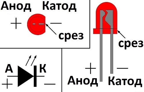
Take a look inside the LED: the large electrode is the cathode, its - to the minus, the small electrode, which looks like just the end of the leg - to the plus. And next to the cathode, the LED lens has a flat cut.
Do not keep the soldering iron on the leg for a long time
Solder the LED leads carefully and quickly, because the semiconductor junction is very afraid of excess heat, so you need to briefly touch the soldering iron with its tip to the soldered leg, and then take the soldering iron aside. It is better to hold the soldered leg of the LED with tweezers during the soldering process to ensure that heat is removed from the leg just in case.
Resistor required when testing LED

We come to the most important thing - how to connect the LED to a power source. If you want, then you should not directly connect it to the battery or to the power supply. If your power supply is 12 volts, then use a 1 kΩ resistor in series with the LED under test for safety net.
Don't forget about polarity - long output to plus, the output from the large internal electrode to minus. If you do not use a resistor, the LED will quickly burn out if you accidentally exceed Rated voltage, a large current will flow through the p-n junction, and the LED will almost immediately fail.
LEDs come in a variety of colors, but the color of the glow is not always determined by the color of the LED lens. White, red, blue, orange, green or yellow - the lens can be transparent, and turn it on - it will turn out to be red or blue. Blue and white LEDs are the most expensive. In general, the color of the glow of the LED is primarily affected by the composition of the semiconductor, and as a secondary factor, the color of the lens.

Finding the value of the resistor for the LED
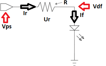
The resistor is connected in series with the LED. The function of the resistor is to limit the current, make it close to the LED rating, so that the LED does not instantly burn out, and would work in the normal nominal mode. We take into account the following initial data:
Vps - power supply voltage;
Vdf is the forward voltage drop across the LED in normal mode;
If - rated current of the LED in normal glow mode.
Now, before finding , we note that the current in the series circuit will be constant, the same in each element: the current If through the LED will be equal to the current Ir through the limiting resistor.
Hence Ir = If. But Ir = Ur/R - according to Ohm's law. And Ur \u003d Vps-Vdf. Thus R = Ur/Ir = (Vps-Vdf)/If.
That is, knowing the voltage of the power supply, the voltage drop across the LED and its rated current, you can easily select the appropriate limiting resistor.
If the resistance value found cannot be selected from the standard series of resistor values, then a resistor of a slightly larger value is taken, for example, instead of the found 460 Ohms, they take 470 Ohms, which are always easy to find. The brightness of the LED will decrease very slightly.
Resistor selection example:
Let's say there is a 12 volt power supply, and an LED that needs 1.5 volts and 10 mA to glow normally. Let's choose a quenching resistor. The resistor should drop 12-1.5 = 10.5 volts, and the current in the series circuit (power supply, resistor, LED) should be 10 mA, hence from Ohm's Law: R = U / I = 10.5 / 0.010 = 1050 ohm. We choose 1.1 kOhm.
How big should the resistor be? If R \u003d 1100 Ohm, and the current is 0.01 A, then, according to the Joule-Lenz law, thermal energy Q \u003d I * I * R \u003d 0.11 J will be released on the resistor every second, which is equivalent to 0.11 W. A 0.125 W resistor will do, even a margin will remain.
Serial connection of LEDs
If your goal is to connect several LEDs into a single light source, then it is best to connect in series. This is necessary so that each LED does not have its own resistor, in order to avoid unnecessary energy losses. The most suitable for serial connection are LEDs of the same type, from the same batch.
Suppose you need to connect in series 8 LEDs of 1.4 volts with a current of 0.02 A to connect to a 12 volt power source. Obviously, the total current will be 0.02 A, but the total voltage will be 11.2 volts, so 0.8 volts at a current of 0.02 A should be dissipated by the resistor. R \u003d U / I \u003d 0.8 / 0.02 \u003d 40 ohms. We select a 43 ohm resistor of minimum power.
Parallel connection of LED strings is not the best option

If there is a choice, then the LEDs are best connected in series, not in parallel. If you connect several LEDs in parallel through one common resistor, then due to the spread in the parameters of the LEDs, each of them will not be on an equal footing with the others, some will glow brighter, taking more current, and some, on the contrary, will be dimmer. As a result, some of the LEDs will burn out earlier due to the rapid degradation of the crystal. It is better to connect LEDs in parallel, if there is no alternative, apply a different limiting resistor to each chain.
The main parameter that affects the life of the LED is electricity, the value of which is strictly normalized for each type of LED element. One common way to limit the maximum current is to use a limiting resistor. The resistor for the LED can be calculated without the use of complex calculations based on Ohm's law, using the technical values \u200b\u200bof the diode parameters and the voltage in the turn-on circuit.

Features of turning on the LED
Working on the same principle as rectifier diodes, light emitting elements, however, have distinctive features. The most important ones are:
- Extremely negative sensitivity to reverse polarity voltage. An LED connected to the circuit with the wrong polarity fails almost instantly.
- Narrow range of permissible operating current through the p-n junction.
- Dependence of transition resistance on temperature, which is typical for most semiconductor elements.
On the last paragraph should dwell in more detail, since it is the main one for calculating the quenching resistor. The documentation for the radiating elements indicates the permissible range of the rated current, in which they remain operational and provide the specified radiation characteristics. Understating the value is not fatal, but leads to some decrease in brightness. Starting from a certain limit value, the passage of current through the transition stops, and the glow will be absent.
Exceeding the current first leads to an increase in the brightness of the glow, but the service life is sharply reduced. Further increase leads to the failure of the element. Thus, the selection of a resistor for an LED aims to limit the maximum admissible current in the worst conditions.
The voltage at a semiconductor junction is limited by the physical processes on it and is in a narrow range of about 1-2 V. 12 Volt light emitting diodes, often installed on cars, may contain a chain of series-connected elements or a limiting circuit included in the design.
Why do you need a resistor for the LED
Using limiting resistors when turning on LEDs is, although not the most effective, but the easiest and cheapest solution to limit the current within acceptable limits. Circuit solutions that allow you to stabilize the current in the emitter circuit with high accuracy are quite difficult to repeat, and ready-made ones have a high cost.
The use of resistors allows you to perform lighting and backlighting on your own. The main thing is the ability to use measuring instruments and minimal soldering skills. A well-designed limiter, taking into account possible tolerances and temperature fluctuations, is able to provide normal functioning LEDs throughout the entire declared service life at minimal cost.
Parallel and serial connection of LEDs
In order to combine the parameters of the power circuits and the characteristics of the LEDs, serial and parallel connection of several elements is widespread. Each type of connection has both advantages and disadvantages.
Parallel connection
The advantage of such a connection is the use of only one limiter for the entire circuit. It should be noted that this dignity is the only one, so the parallel connection is almost never found, with the exception of low-grade industrial products. The disadvantages are:
- The power dissipation on the limiting element increases in proportion to the number of LEDs connected in parallel.
- The scatter of the parameters of the elements leads to uneven distribution of currents.
- The burnout of one of the emitters leads to an avalanche-like failure of all the others due to an increase in the voltage drop across the group connected in parallel.
The connection somewhat increases the operational properties, where the current through each radiating element is limited by a separate resistor. More precisely, it is a parallel connection of separate circuits consisting of LEDs with limiting resistors. The main advantage is greater reliability, since the failure of one or more elements does not in any way affect the operation of the others.
The disadvantage is the fact that due to the spread of the LED parameters and the technological tolerance for the resistance value, the brightness of the glow of individual elements can vary greatly. Such a scheme contains a large number of radio elements.
Parallel connection with individual limiters finds use in low voltage circuits, starting with a minimum, limited by the voltage drop at the p-n junction.


Series connection
The series connection of radiating elements has become the most widespread, since the undoubted advantage of a series circuit is the absolute equality of the current passing through each element. Since the current through the single limiting resistor and through the diode is the same, then the power dissipation will be minimal.
A significant drawback is that the failure of at least one of the elements will lead to the inoperability of the entire chain. Serial connection requires higher voltage, minimum value which grows in proportion to the number of included elements.


mixed inclusion
The use of a large number of emitters is possible when performing a mixed connection, when several chains connected in parallel are used, and a series connection of one limiting resistor and several LEDs.
The burnout of one of the elements will lead to the inoperability of only one circuit in which this element is installed. The rest will function properly.
Resistor calculation formulas
The calculation of resistor resistance for LEDs is based on Ohm's law. The initial parameters for how to calculate the resistor for the LED are:
- circuit voltage;
- operating current of the LED;
- voltage drop across the emitting diode (LED supply voltage).
The resistance value is determined from the expression:
where U is the voltage drop across the resistor and I is the forward current through the LED.
The voltage drop of the LED is determined from the expression:
U \u003d Upit - Usv,
where Upit is the circuit voltage, and Usv is the nameplate voltage drop across the radiating diode.
Calculating an LED for a resistor gives a resistance value that will not be in the standard range of values. You need to take a resistor with a resistance closest to the calculated value on the larger side. This takes into account the possible increase in voltage. It is better to take the value next in the series of resistances. This will slightly reduce the current through the diode and reduce the brightness of the glow, but at the same time, any change in the magnitude of the supply voltage and diode resistance (for example, when the temperature changes) is leveled.
Before choosing a resistance value, you should evaluate the possible decrease in current and brightness compared to that specified by the formula:
(R - Rst)R 100%
If the value obtained is less than 5%, then you need to take a larger resistance, if from 5 to 10%, then you can limit yourself to a smaller one.
Not less than important parameter, affecting the reliability of work - the dissipated power of the current-limiting element. The current passing through a section with resistance causes it to heat up. To determine the power that will be dissipated, use the formula:
Use a limiting resistor whose power dissipation will exceed the calculated value.
There is an LED with a voltage drop across it of 1.7 V with a nominal current of 20 mA. It must be connected to a 12 V circuit.
The voltage drop across the limiting resistor is:
U = 12 - 1.7 = 10.3 V
Resistor resistance:
R \u003d 10.3 / 0.02 \u003d 515 ohms.
The nearest higher value in the standard range is 560 ohms. With this value, the decrease in current compared to the set value is slightly less than 10%, so there is no need to take a larger value.
Dissipated power in watts:
P = 10.3 10.3/560 = 0.19 W
Thus, for this circuit, you can use an element with a permissible dissipation power of 0.25 W.
Connecting the LED strip
LED strips are available for different supply voltages. On the tape is a circuit of series-connected diodes. The number of diodes and the resistance of the limiting resistors depend on the supply voltage of the tape.
The most common types of LED strips are designed to be connected to a 12 V circuit. Using a higher voltage value for operation is also possible here. For the correct calculation of resistors, it is necessary to know the current flowing through a single section of the tape.
An increase in the length of the tape causes a proportional increase in current, since the minimum sections are technologically connected in parallel. For example, if the minimum length of a segment is 50 cm, then a 5 m tape out of 10 such segments will have a 10-fold increase in current consumption.


Many users when connecting diode tape or a separate LED to the power source, they find that the element refuses to burn as it should, or even worse, it simply burns out.
The thing is that the node is connected to the power supply without proper protection and preliminary calculations.
This task, oddly enough, is solved very easily. There are many online tools for automatically performing calculations, but not all such results can be trusted. And it is best to first understand the principles, and then calculate everything manually for reliability, especially since this operation is quite simple.
What you need to know
If you suddenly do not know the three laws (rules) of Kirchhoff for electrical circuits, then calm down, you will not need their knowledge. The only necessary formula is described by Ohm's law for the chain section.
She looks like this.
It reads like this: the current strength of a circuit section is directly proportional to the voltage and inversely proportional to the resistance on it. Or so: the current strength is equal to the voltage divided by the resistance (the most simplified version).
The formula is easily converted to others if necessary.
We will use the latter in our calculations.
In the original, the formula is a little more complicated, since it takes into account the internal resistance and EMF of the current source itself.
But we can safely neglect them in the given conditions of the problem.
Thus, we will need the following parameters:
1.Output characteristics of current and voltage at the connection point. If this is a section of the circuit, then the values \u200b\u200bare best measured with an ammeter and a voltmeter. If a direct connection is made to a current source (it can be a rectifier, a battery or an accumulator), then it will be enough to know their nominal values indicated in the marking or accompanying documentation.
2.Maximum (maximum allowable) and nominal values of supply voltage and current for the connected LED. You can recognize them most often by marking the radio component. If it is an LED strip, then in the accompanying documentation.
Calculation in series connection
In fact, the series connection of LEDs, coupled with a limiting resistance, is the most commonly used scheme. So, for example, an LED strip is nothing more than a set of LEDs connected in series.
Rice. 1. LED strip
For clarity, the schematic diagram.

Rice. 2. circuit diagram
In this case, the resistor will act as a voltage divider and current limiter.
The formula will look like this.
R ogr \u003d (U pit - U sd) / I sd
- R ogr is the value of the limiting resistor;
- U pit - voltage at the power source (or at the section of the circuit where the "diode-resistor" block is connected);
- U sd - rated operating voltage of the LED (see the technical documentation);
- I sd - the nominal (working) value of the current on the LED (see the technical documentation for the LED).
If you need to connect several diodes at once, then the formula will look like this.
R limit = (U pit - N U sd) / I sd
Where N is the number of LEDs connected in series.
For LED strips, it is necessary to operate with the parameters of not one element (diode), but the entire section at once (based on the standards for 1 running meter, multiplied by the number of actually used meters).
With this arrangement of parts, it is allowed to connect only diodes that are identical in parameters (they themselves act as voltage dividers and therefore someone simply does not have enough power).
Calculation example
Let U pit \u003d 24 V, U sd \u003d 1.8 V (in most LEDs this range is 1.5 - 2V), I sd \u003d 10 mA (or 0.01 A, which also corresponds to the normal values \u200b\u200bof widely used diode models). Then substituting into the formula we get:
R limit \u003d (24 - 1.8) / 0.01 \u003d 22.2 / 0.01 \u003d 2220 (Ohm)
Or 2.22 kOhm (kilo-ohm).
If there are 5 diodes, then the result will be as follows:
R limit \u003d (24 - 1.8 5) / 0.01 \u003d 15 / 0.01 \u003d 1500 (Ohm)
Resistors are available only in fixed values. You can get what you want by connecting several different resistances in series (then their value will add up) or in parallel (calculation formula below).
![]()
Before installation, it is best to measure the indicator with an ohmmeter.
Inclusion in the scheme can be performed as follows.

Rice. 3. Parallel connection of LEDs
In this case, the voltage in each "resistor-LED" section is the same (with parallel connection, only the current strength changes), which means that the calculation will be carried out as in the examples above.
Calculation of power dissipation on the resistor
Due to the fact that the greater the resistance of the element to the current passing through it, the more work the latter does. And work is always accompanied by the release of energy, which means that the resistor, as a blocking element, will inevitably heat up.
To prevent the resistance from failing earlier than necessary, it is necessary to correctly calculate the energy received and ensure its uniform dissipation.
Since the resistor is connected in series in the circuit, the current strength in the "diode-resistor" section is the same everywhere and does not exceed the nominal value that we used in the calculations, that is, I sd (the diode's own resistance in this case can be neglected, since it is negligible small, it turns out that the resistance of the circuit section is very close to the value of the limiting resistor).
P (W) \u003d I 2 (A) R (Ohm)
As an example.
For a resistance of 2220 ohms with a current strength of 0.01 A in the circuit section
The LED has very little internal resistance, if connected directly to the power supply, the current will be high enough to burn it out. Copper or gold threads with which the crystal is connected to external findings, can withstand small jumps, but if they are strongly exceeded, they burn out and power stops flowing to the crystal. Online calculation The resistor for an LED is made based on its rated operating current.

- 1. Online calculator
- 2. Main parameters
- 3. Features of cheap ICE
Online calculator

Make a wiring diagram beforehand to avoid calculation errors. The online calculator will show you the exact resistance in ohms. As a rule, it turns out that resistors with this rating are not available, and you will be shown the nearest standard rating. If it is not possible to make an accurate selection of resistance, then use a larger denomination. A suitable value can be made by connecting the resistance in parallel or in series. The calculation of the resistance for the LED can be omitted if you use a powerful variable or tuning resistor. The most common type is 3296 at 0.5W. When using a 12V power supply, up to 3 LEDs can be connected in series.

Resistors come in different accuracy classes, 10%, 5%, 1%. That is, their resistance can error within these limits in a positive or negative direction.
Do not forget to take into account the power of the current-limiting resistor, this is its ability to dissipate a certain amount of heat. If it is small, then it will overheat and fail, thereby breaking the electrical circuit.
To determine the polarity, you can apply a small voltage or use the diode test function on the multimeter. Different from the resistance measurement mode, usually supplied from 2V to 3V.
main parameters

Also, when calculating LEDs, one should take into account the spread of parameters, for cheap ones they will be maximum, for expensive ones they will be more the same. To check this parameter, you must enable them under equal conditions, that is, sequentially. By reducing the current or voltage, reduce the brightness to slightly glowing dots. Visually you will be able to judge, some will glow brighter, others dimly. The more evenly they burn, the less spread. The LED resistor calculator assumes that the characteristics of the LED chips are ideal, that is, the difference is zero.

The drop voltage for common low-power models up to 10W can be from 2V to 12V. As the power increases, the number of crystals in the COB diode increases, each has a drop. Crystals are connected in series in series, then they are combined into parallel circuits. At powers from 10W to 100W, the reduction grows from 12V to 36V.
This setting must be specified in technical specifications LED chip and depends on the purpose:
- colors blue, red, green, yellow;
- tricolor RGB;
- four-color RGBW;
- two-tone, warm and cold white.
Features of cheap ICE

Before choosing a resistor for an LED on online calculator e, you should make sure the parameters of the diodes. The Chinese on Aliexpress sell a lot of led, passing them off as branded ones. The most popular models are SMD3014, SMD 3528, SMD2835, SMD 5050, SMD5630, SMD5730. The worst stuff is usually done under the Epistar brand.

For example, most often the Chinese cheat on SMD5630 and SMD5730. The numbers in the marking indicate only the size of the case 5.6mm by 3.0mm. In branded ones, such a large case is used to install powerful crystals at 0.5W, therefore, buyers of SMD5630 diodes are directly associated with a power of 0.5W. The cunning Chinese takes advantage of this, and installs a cheap and weak crystal in the 5630 case at an average of 0.1W, while indicating an energy consumption of 0.5W.
 Chinese LED lamp corn
good example there will be car lamps and LED corn, in which a large number of weak and low-quality LED chips are supplied. The average buyer believes that the more LEDs, the better it shines and the higher the power.
 Automobile lamps on the weakest ice 0.1W
To save money, my LED colleagues are looking for decent LEDs on Aliexpress. They are looking for a good seller who promises certain parameters, they order, they wait for delivery for a month. After the tests, it turns out that the Chinese seller cheated and sold junk. You'll be lucky if decent diodes come for the seventh time, and not junk. Usually they will make 5 orders, and having not achieved a result, they go to place an order in a domestic store that can make an exchange.