Multivibrators are another form of oscillators. The generator is electronic circuit, which is capable of supporting an AC signal at the output. It can generate square wave, linear or pulse waveforms. To oscillate, the generator must satisfy two Barkhausen conditions:
T is the loop gain, it should be slightly greater than unity.
The cycle phase shift must be 0 degrees or 360 degrees.
To fulfill both conditions, the oscillator must have some form of amplifier, and part of its output must be regenerated to the input. If the amplifier gain is less than one, the circuit will not oscillate, and if it is greater than one, the circuit will be overloaded and produce a distorted waveform. A simple generator can generate a sine wave, but cannot generate a square wave. A square wave can be generated using a multivibrator.
A multivibrator is a form of generator that has two stages, thanks to which we can get an output from any of the states. These are basically two amplifier circuits arranged with regenerative feedback. In this case, none of the transistors conducts at the same time. Only one transistor conducts at a time, while the other is in the off state. Some circuits have certain states; a state with a fast transition is called switching processes, where rapid change current and voltage. This switch is called trigger. Hence, we can run the circuit inside or outside.
Schemes have two states.
One of them is a stable state, in which the circuit remains forever without any start.
The other state is unstable: in this state, the circuit remains for a limited period of time without any external trigger and switches to another state. Therefore, the use of multivibartors is carried out in two states of circuits, such as timers and flip-flops.
Unstable multivibrator using a transistor
It is a free-running oscillator that continuously switches between two unstable states. In the absence of an external signal, the transistors alternately switch from the off state to the saturation state at a frequency determined by the RC time constants of the coupling circuits. If these time constants are equal (R and C are equal), then a square wave with a frequency of 1/1.4 RC will be generated. Therefore, an unstable multivibrator is called a pulse generator or square wave generator. The greater the value of the base load of R2 and R3 in relation to the collector load of R1 and R4, the greater the current gain and the sharper the signal edge will be.
The basic principle of operation of an astable multivibrator is a small change in the electrical properties or characteristics of a transistor. This difference causes one transistor to turn on faster than the other the first time power is applied, causing oscillation.
Scheme Explanation
The astable multivibrator consists of two cross-coupled RC amplifiers.
The circuit has two unstable states
When V1=LOW and V2=HIGH then Q1 ON and Q2 OFF
When V1=HIGH and V2=LOW, Q1 is OFF. and Q2 ON.
In this case, R1 = R4, R2 = R3, R1 must be greater than R2
C1=C2
When the circuit is first turned on, none of the transistors are turned on.
The base voltage of both transistors starts to increase. Any of the transistors turns on first due to the difference in doping and electrical characteristics of the transistor.
Rice. one: circuit diagram operation of a transistor unstable multivibrator
We can't tell which transistor conducts first, so we assume that Q1 conducts first and Q2 is off (C2 is fully charged).
Q1 conducts and Q2 is off, hence VC1 = 0V since all current is to ground due to Q1's short circuit, and VC2 = Vcc since all voltage on VC2 is dropped due to TR2 open circuit (equal to supply voltage) .
because of high voltage VC2 capacitor C2 starts charging through Q1 through R4, and C1 starts charging through R2 through Q1. The time required to charge C1 (T1 = R2C1) is longer than the time required to charge C2 (T2 = R4C2).
Since the right plate of C1 is connected to the base of Q2 and is being charged, this plate has a high potential, and when it exceeds 0.65 V, it turns on Q2.
Since C2 is fully charged, its left plate is at -Vcc or -5V and is connected to Q1's base. Therefore, it turns off Q2
TR Now TR1 is off and Q2 conducts, therefore VC1 = 5V and VC2 = 0V. The left plate of C1 was previously at -0.65V, which starts to rise to 5V and connects to the collector of Q1. C1 first discharges from 0 to 0.65V and then starts charging through R1 through Q2. During charging, the right plate of C1 has a low potential, which turns off Q2.
The right plate of C2 is connected to the collector of Q2 and is pre-positioned at +5V. So C2 first discharges from 5V to 0V and then starts charging through R3. The left plate of C2 is at a high potential during charging, which turns on Q1 when it reaches 0.65V.
Rice. 2: Schematic diagram of the operation of a transistor astable multivibrator
![]()
Now Q1 is conducting and Q2 is off. The above sequence is repeated and we get a signal at both collectors of the transistor that is out of phase with each other. To obtain a perfect square wave with any transistor collector, we take as the collector resistance of the transistor, the base resistance, i.e. (R1 = R4), (R2 = R3), and also the same value of the capacitor, which makes our circuit symmetrical. Therefore, the duty cycle for the low and high value of the output signal is the same that generates a square wave
Constant The time constant of the waveform depends on the base resistance and collector of the transistor. We can calculate its time period by: Time Constant = 0.693RC
The principle of operation of the multivibrator in the video with an explanation
In this video tutorial of the Soldering TV channel, we will show how the elements are interconnected electrical circuit and get acquainted with the processes taking place in it. The first circuit, on the basis of which the principle of operation will be considered, is a transistor multivibrator circuit. The circuit can be in one of two states and periodically changes from one to the other.
Analysis of 2 states of the multivibrator.
All we are seeing right now is two LEDs flashing alternately. Why is this happening? Consider first first state.
The first transistor VT1 is closed, and the second transistor is fully open and does not prevent the flow of collector current. The transistor at this moment is in saturation mode, which reduces the voltage drop across it. And so the right LED is lit at full strength. Capacitor C1 was discharged at the first moment of time, and the current passed freely to the base of transistor VT2, completely opening it. But after a moment, the capacitor begins to quickly charge the base current of the second transistor through the resistor R1. After it is fully charged (and as you know, a fully charged capacitor does not pass current), then the transistor VT2 closes as a result and the LED goes out.
The voltage across the capacitor C1 is equal to the product of the base current and the resistance of the resistor R2. Let's go back in time. While the transistor VT2 was open and the right LED was on, the capacitor C2, previously charged in the previous state, begins to slowly discharge through the open transistor VT2 and the resistor R3. Until it is discharged, the voltage at the base of VT1 will be negative, which completely blocks the transistor. The first LED is off. It turns out that by the time the second LED fades out, the capacitor C2 has time to discharge and becomes ready to pass current to the base of the first transistor VT1. By the time the second LED stops lighting, the first LED lights up.
BUT in the second state the same thing happens, but on the contrary, the transistor VT1 is open, VT2 is closed. The transition to another state occurs when the capacitor C2 is discharged, the voltage across it decreases. When fully discharged, it starts charging in the opposite direction. When the voltage at the base-emitter junction of transistor VT1 reaches a voltage sufficient to open it, approximately 0.7 V, this transistor will start to open and the first LED will light up.
Let's look at the diagram again.
The capacitors are charged through resistors R1 and R4, and discharged through R3 and R2. Resistors R1 and R4 limit the current of the first and second LEDs. Not only the brightness of the LEDs depends on their resistance. They also determine the charging time of the capacitors. The resistance R1 and R4 is selected much smaller than R2 and R3, so that the capacitors are charged faster than they are discharged. The multivibrator is used to obtain rectangular pulses, which are taken from the collector of the transistor. In this case, the load is connected in parallel to one of the collector resistors R1 or R4.
The graph shows the rectangular pulses generated by this circuit. One of the regions is called the pulse front. The front has a slope, and the longer the charging time of the capacitors, the greater this slope will be.

If the same transistors, capacitors of the same capacity are used in the multivibrator, and if the resistors have symmetrical resistances, then such a multivibrator is called symmetrical. It has the same pulse duration and pause duration. And if there are differences in the parameters, then the multivibrator will be asymmetrical. When we connect the multivibrator to the power source, then at the first moment of time both capacitors are discharged, which means that current will flow to the base of both capacitors and an unsteady operating mode will appear, in which only one of the transistors should open. Since these circuit elements have some errors in ratings and parameters, one of the transistors will open first, and the multivibrator will start.
If you want to simulate this circuit in the Multisim program, then you need to set the values \u200b\u200bof the resistors R2 and R3 so that their resistances differ by at least a tenth of an ohm. Do the same with the capacitance of the capacitors, otherwise the multivibrator may not start. In the practical implementation of this circuit, I recommend supplying voltage from 3 to 10 volts, and now you will find out the parameters of the elements themselves. Provided that the KT315 transistor is used. Resistors R1 and R4 do not affect the pulse frequency. In our case, they limit the current of the LED. The resistance of resistors R1 and R4 can be taken from 300 ohms to 1 kOhm. The resistance of resistors R2 and R3 is from 15 kOhm to 200 kOhm. The capacitance of capacitors is from 10 to 100 microfarads. Imagine a table with the values of resistance and capacitance, which shows the approximate expected frequency of the pulses. That is, to get a pulse with a duration of 7 seconds, that is, the duration of the glow of one LED, equal to 7 seconds, you need to use resistors R2 and R3 with a resistance of 100 kOhm and a capacitor with a capacity of 100 microfarads.
Conclusion.
The timing elements of this circuit are resistors R2, R3 and capacitors C1 and C2. The lower their ratings, the more often the transistors will switch, and the more often the LEDs will flicker.
The multivibrator can be implemented not only on transistors, but also on the basis of microcircuits. Leave your comments, do not forget to subscribe to the Soldering TV channel on YouTube so as not to miss new interesting videos.
More interesting about the radio transmitter.
This lesson will be devoted to a rather important and popular topic, about multivibrators and their application. If I tried to just list where and how self-oscillating symmetrical and asymmetrical multivibrators are used, this would require a decent number of book pages. There is, perhaps, no such branch of radio engineering, electronics, automation, impulse or computer technology, where such generators would not be used. This lesson will give theoretical information about these devices, and in the end, I will give some examples of their practical use in relation to your creativity.
Self-oscillating multivibrator
Multivibrators are electronic devices that generate electrical vibrations that are close in shape to a rectangular one. The spectrum of oscillations generated by the multivibrator contains many harmonics - also electrical oscillations, but multiples of the fundamental frequency oscillations, which is reflected in its name: "multi - many", "vibration - oscillate".
Consider the circuit shown in (Fig. 1a). Do you recognize? Yes, this is a two-stage circuit transistor amplifier 3H with headphone output. What happens if the output of such an amplifier is connected to its input, as shown by the dashed line in the diagram? A positive feedback occurs between them and the amplifier will self-excite and become an oscillation generator audio frequency, and in telephones we will hear a low-pitched sound. With such a phenomenon in receivers and amplifiers, they are decisively fighting, but for automatically operating devices it turns out to be useful.
Now look at (Fig. 1b). On it you see a circuit of the same amplifier, covered positive feedback , as in (Fig. 1, a), only its outline is somewhat changed. This is how the circuits of self-oscillatory, i.e., self-excited multivibrators, are usually drawn. Experience is perhaps the best method of knowing the essence of the action of one or another electronic device. You have proven this many times. And now, in order to better understand the operation of this universal device - an automatic machine, I propose to conduct an experiment with it. You can see a schematic diagram of a self-oscillating multivibrator with all the data of its resistors and capacitors in (Fig. 2, a). Mount it on a breadboard. Transistors must be low-frequency (MP39 - MP42), since high-frequency transistors have a very small breakdown voltage of the emitter junction. Electrolytic capacitors C1 and C2 - type K50 - 6, K50 - 3 or their imported analogues on the Rated voltage 10 - 12 V. The resistance of the resistors may differ from those indicated in the diagram up to 50%. It is only important that the ratings of the load resistors Rl, R4 and the base resistors R2, R3 are possibly the same. For power, use the Krona battery or PSU. In the collector circuit of any of the transistors, turn on a milliammeter (PA) for a current of 10 - 15 mA, and connect a high-resistance DC voltmeter (PU) to a voltage of up to 10 V to the emitter-collector section of the same transistor. After checking the installation and especially carefully the polarity of switching on electrolytic capacitors, connect a power source to the multivibrator. What do the meters show? Milliammeter - sharply increasing to 8 - 10 mA, and then also sharply decreasing almost to zero, the current of the collector circuit of the transistor. The voltmeter, on the contrary, either decreases almost to zero, or increases to the voltage of the power source, the collector voltage. What do these measurements say? The fact that the transistor of this arm of the multivibrator operates in the switching mode. The largest collector current and at the same time the smallest voltage on the collector correspond to the open state, and the smallest current and the largest collector voltage correspond to the closed state of the transistor. The transistor of the second arm of the multivibrator works exactly the same way, but, as they say, with 180° phase shift : when one of the transistors is open, the other is closed. It is easy to verify this by including the same milliammeter in the collector circuit of the transistor of the second arm of the multivibrator; the arrows of the measuring instruments will alternately deviate from the zero marks of the scales. Now, using a clock with a second hand, count how many times per minute the transistors go from open to closed. Approximately 15 - 20 times. This is the number of electrical oscillations generated by the multivibrator per minute. Therefore, the period of one oscillation is 3 - 4 s. Continuing to follow the arrow of the milliammeter, try to depict these fluctuations graphically. On the horizontal axis of ordinates, plot on a certain scale the time intervals for the transistor to be in the open and closed states, and along the vertical axis, the collector current corresponding to these states. You will get approximately the same graph as the one shown in Fig. 2b.
So, it can be considered that the multivibrator generates electrical oscillations of a rectangular shape. In a multivibrator signal, regardless of which output it is taken from, current pulses and pauses between them can be distinguished. The time interval from the moment a single current (or voltage) pulse appears until the next pulse of the same polarity appears is usually called the pulse repetition period T, and the time between pulses with a pause duration Tn - Multivibrators generating pulses whose duration Tn is equal to the pauses between them are called symmetrical . Therefore, the experienced multivibrator you have assembled - symmetric. Replace capacitors C1 and C2 with other 10 to 15 uF capacitors. The multivibrator remained symmetrical, but the frequency of the oscillations generated by it increased by 3-4 times - up to 60-80 per 1 min, or, what is the same, up to about a frequency of 1 Hz. The arrows of the measuring instruments barely have time to follow the changes in currents and voltages in the transistor circuits. And if capacitors C1 and C2 are replaced with paper capacitances of 0.01 - 0.05 microfarads? How will the arrows of measuring instruments now behave? Having deviated from the zero marks of the scales, they stand still. Maybe the generation is broken? Not! It's just that the oscillation frequency of the multivibrator has increased to several hundred hertz. These are fluctuations in the audio frequency range, which DC devices can no longer fix. You can detect them using a frequency meter or headphones connected through a capacitor with a capacity of 0.01 - 0.05 microfarads to any of the outputs of the multivibrator or by connecting them directly to the collector circuit of any of the transistors instead of a load resistor. On the phones, you will hear a low tone sound. What is the working principle of a multivibrator? Let's return to the diagram in Fig. 2, a. At the moment the power is turned on, the transistors of both arms of the multivibrator open, since negative bias voltages are applied to their bases through the corresponding resistors R2 and R3. At the same time, the coupling capacitors begin to charge: C1 - through the emitter junction of the transistor V2 and the resistor R1; C2 - through the emitter junction of transistor V1 and resistor R4. These capacitor charging circuits, being voltage dividers of the power supply, create on the bases of the transistors (relative to the emitters) negative voltages that increase in value, tending to open the transistors more and more. Opening a transistor causes the negative voltage at its collector to drop, which causes the negative voltage at the base of the other transistor to drop, turning it off. Such a process occurs immediately in both transistors, however, only one of them closes, on the basis of which a higher positive voltage, for example, due to the difference in the current transfer coefficients h21e of the resistor and capacitor ratings. The second transistor remains open. But these states of transistors are unstable, because the electrical processes in their circuits continue. Let's assume that after some time after turning on the power, the transistor V2 turned out to be closed, and the transistor V1 turned out to be open. From this moment, the capacitor C1 begins to discharge through the open transistor V1, the resistance of the emitter-collector section of which is low at this time, and the resistor R2. As the capacitor C1 discharges, the positive voltage at the base of the closed transistor V2 decreases. As soon as the capacitor is completely discharged and the voltage at the base of the transistor V2 becomes close to zero, a current appears in the collector circuit of this now opening transistor, which acts through the capacitor C2 on the base of the transistor V1 and lowers the negative voltage on it. As a result, the current flowing through the transistor V1 begins to decrease, and through the transistor V2, on the contrary, increases. This causes transistor V1 to turn off and transistor V2 to turn on. Now the capacitor C2 will start to discharge, but through the open transistor V2 and the resistor R3, which ultimately leads to the opening of the first and closing of the second transistor, etc. Transistors interact all the time, as a result of which the multivibrator generates electrical oscillations. The oscillation frequency of the multivibrator depends both on the capacitance of the coupling capacitors, which you have already checked, and on the resistance of the base resistors, as you can see right now. Try, for example, to replace the basic resistors R2 and R3 with high-resistance resistors. The oscillation frequency of the multivibrator will decrease. Conversely, if their resistances are less, the oscillation frequency will increase. Another experience: disconnect the upper (according to the diagram) terminals of the resistors R2 and R3 from the negative conductor of the power source, connect them together, and between them and the negative conductor, turn on a variable resistor with a resistance of 30 - 50 kOhm with a rheostat. By turning the axis of the variable resistor, you can change the oscillation frequency of the multivibrators within a fairly wide range. The approximate oscillation frequency of a symmetrical multivibrator can be calculated using the following simplified formula: F = 700 / (RC), where f is the frequency in hertz, R is the resistance of the base resistors in kiloohms, C is the capacitance of the coupling capacitors in microfarads. Using this simplified formula, calculate what frequencies your multivibrator generated. Let's return to the initial data of the resistors and capacitors of the experimental multivibrator (according to the diagram in Fig. 2, a). Replace capacitor C2 with a capacitor with a capacity of 2 - 3 μF, turn on a milliammeter in the collector circuit of transistor V2, following its arrow, graphically depict the current fluctuations generated by the multivibrator. Now the current in the collector circuit of transistor V2 will appear in shorter pulses than before (Fig. 2, c). The duration of the pulses Th will be approximately as many times less than the pauses between the pulses Th, by how much the capacitance of the capacitor C2 has decreased compared to its previous capacitance. And now turn the same (or such) milliammeter into the collector circuit of transistor V1. What shows measuring device? Also current pulses, but their duration is much longer than the pauses between them (Fig. 2, d). What happened? By reducing the capacitance of capacitor C2, you violated the symmetry of the arms of the multivibrator - it became asymmetrical . Therefore, the vibrations generated by it became asymmetrical : in the collector circuit of the transistor V1, the current appears in relatively long pulses, in the collector circuit of the transistor V2, in short pulses. From Output 1 of such a multivibrator, you can take short, and from Output 2 - long voltage pulses. Temporarily swap capacitors C1 and C2. Now short voltage pulses will be at Output 1, and long voltage pulses at Output 2. Count (by the clock with a second hand) how many electrical impulses per minute this version of the multivibrator generates. About 80. Increase the capacitance of capacitor C1 by connecting a second electrolytic capacitor with a capacity of 20 - 30 microfarads in parallel with it. The pulse repetition rate will decrease. And if, on the contrary, the capacitance of this capacitor is reduced? The pulse repetition rate should increase. There is, however, another way to regulate the pulse repetition rate - by changing the resistance of the resistor R2: with a decrease in the resistance of this resistor (but not less than 3 - 5 kOhm, otherwise the transistor V2 will be open all the time and the self-oscillating process will be disrupted), the pulse repetition frequency should increase, and with an increase in its resistance, on the contrary, decrease. Check it out empirically - is it so? Choose a resistor of such a value that the number of pulses in 1 minute is exactly 60. The milliammeter needle will oscillate at a frequency of 1 Hz. The multivibrator in this case will become, as it were, an electronic clock mechanism that counts seconds.
Waiting multivibrator
Such a multivibrator generates current (or voltage) pulses when triggering signals are applied to its input from another source, for example, from a self-oscillating multivibrator. In order to turn the self-oscillating multivibrator, with which you have already conducted experiments in this lesson (according to the diagram in Fig. 2, a), into a waiting multivibrator, you must do the following: remove the capacitor C2, and instead of it, connect a resistor between the collector of the transistor V2 and the base of the transistor V1 (in Fig. 3 - R3) with a resistance of 10 - 15 kOhm; between the base of the transistor V1 and the grounded conductor, connect a series-connected element 332 (G1 or another constant voltage source) and a resistor with a resistance of 4.7 - 5.1 kOhm (R5), but so that the positive pole of the element is connected to the base (through R5); connect a capacitor (in Fig. 3 - C2) with a capacity of 1 - 5 thousand pF to the base circuit of transistor V1, the second output of which will act as a contact for the input control signal. The initial state transistor V1 of such a multivibrator is closed, transistor V2 is open. Check - is it true? The voltage on the collector of a closed transistor should be close to the voltage of the power source, and on the collector of an open transistor it should not exceed 0.2 - 0.3 V. , turn on between the Uin contact and the grounded conductor, literally for a moment, one or two 332 elements connected in series (in the GB1 diagram) or a 3336L battery. Just do not confuse: the negative pole of this external electrical signal must be connected to the contact Uin. In this case, the arrow of the milliammeter should immediately deviate to the value of the highest current of the collector circuit of the transistor, freeze for a while, and then return to its original position in order to wait for the next signal. Repeat this experience several times. The milliammeter with each signal will show an instantaneous increase to 8 - 10 mA and after a while, the collector current of the transistor V1 will also instantly decrease almost to zero. These are single current pulses generated by a multivibrator. And if the battery GB1 is longer to keep connected to the clamp Uin. The same thing will happen as in the previous experiments - only one impulse will appear at the output of the multivibrator. Try it!
And one more experiment: touch the output of the base of the transistor V1 with some metal object taken in your hand. Perhaps, in this case, the waiting multivibrator will work - from the electrostatic charge of your body. Repeat the same experiments, but by including a milliammeter in the collector circuit of the transistor V2. When a control signal is applied, the collector current of this transistor should sharply decrease to almost zero, and then just as sharply increase to the value of the current of the open transistor. This is also a current pulse, but of negative polarity. What is the principle of operation of a waiting multivibrator? In such a multivibrator, the connection between the collector of transistor V2 and the base of transistor V1 is not capacitive, as in a self-oscillating one, but resistive - through resistor R3. A negative bias voltage is applied to the base of the transistor V2 through the resistor R2. The transistor V1 is securely closed by the positive voltage of the G1 element at its base. This state of the transistors is very stable. They can stay in this state for as long as they like. But on the basis of transistor V1, a voltage pulse of negative polarity appeared. From this point on, the transistors go into an unstable state. Under the influence of the input signal, the transistor V1 opens, and the changing voltage on its collector through the capacitor C1 closes the transistor V2. The transistors are in this state until the capacitor C1 is discharged (through the resistor R2 and the open transistor V1, the resistance of which is low at this time). As soon as the capacitor is discharged, the transistor V2 immediately opens, and the transistor V1 closes. From this point on, the multivibrator again finds itself in the original, stable standby mode. In this way, the standby multivibrator has one stable and one unstable state . During an unstable state, it generates one square wave current (voltage), the duration of which depends on the capacitance of the capacitor C1. The larger the capacitance of this capacitor, the longer the pulse duration. So, for example, with a capacitor capacitance of 50 μF, the multivibrator generates a current pulse with a duration of about 1.5 s, and with a capacitor with a capacity of 150 μF - three times more. Through additional capacitors - positive voltage pulses can be taken from output 1, and negative ones from output 2. Can the multivibrator be brought out of standby mode only by a negative voltage pulse applied to the base of transistor V1? No, not only. This can also be done by applying a voltage pulse of positive polarity, but to the base of the transistor V2. So, it remains for you to experimentally check how the capacitance of the capacitor C1 affects the duration of the pulses and the ability to control the waiting multivibrator with positive voltage pulses. How can a standby multivibrator be used practically? Differently. For example, to convert a sinusoidal voltage into rectangular voltage (or current) pulses of the same frequency, or to turn on another device for some time by applying a short-term electrical signal to the input of a waiting multivibrator. How else? Think!
Multivibrator in generators and electronic switches
Electronic call. A multivibrator can be used for a house call, replacing a conventional electric one with it. It can be assembled according to the scheme shown in (Fig. 4). Transistors V1 and V2 operate in a symmetrical multivibrator that generates oscillations with a frequency of about 1000 Hz, and transistor V3 operates in a power amplifier of these oscillations. Amplified vibrations are converted by the dynamic head B1 into sound vibrations. If you use the speakerphone to make a call by turning on primary winding its transition transformer into the collector circuit of transistor V3, its case will accommodate all the bell electronics mounted on the board. The battery will also be located there.
An electronic bell can be installed in the corridor by connecting it with two wires to the S1 button. When you press the - button, sound will appear in the dynamic head. Since power is supplied to the device only during ringing signals, two 3336L batteries connected in series or "Krona" will last for several months of ringing. Set the desired sound tone by replacing capacitors C1 and C2 with capacitors of other capacities. A multivibrator assembled according to the same scheme can be used to study and train in listening to the telegraph alphabet - Morse code. In this case, it is only necessary to replace the button with a telegraph key.
Electronic switch. This device, the circuit of which is shown in (Fig. 5), can be used to switch two Christmas tree garlands powered by an AC mains. The electronic switch itself can be powered by two 3336L batteries connected in series, or from a rectifier that would output a constant voltage of 9–12 V.
The switch circuit is very similar to the electronic bell circuit. But the capacitances of capacitors C1 and C2 of the switch are many times larger than the capacitances of similar bell capacitors. The switch multivibrator, in which transistors V1 and V2 operate, generates oscillations with a frequency of about 0.4 Hz, and the load of its power amplifier (transistor V3) is the winding of the electromagnetic relay K1. The relay has one pair of contact plates for switching. For example, a relay RES - 10 (passport RS4.524.302) or another electromagnetic relay that reliably operates from a voltage of 6 - 8 V at a current of 20 - 50 mA is suitable. When the power is turned on, transistors V1 and V2 of the multivibrator open and close alternately, generating square wave signals. When transistor V2 is turned on, a negative supply voltage is applied through resistor R4 and this transistor is applied to the base of transistor V3, saturating it. In this case, the resistance of the emitter-collector section of transistor V3 decreases to several ohms and almost all the voltage of the power source is applied to the winding of relay K1 - the relay is activated and connects one of the garlands to the network with its contacts. When transistor V2 is closed, the power supply circuit of the base of transistor V3 is broken, and it is also closed, no current flows through the relay coil. At this time, the relay releases the anchor and its contacts, switching, connect the second Christmas tree garland to the network. If you want to change the switching time of the garlands, then replace the capacitors C1 and C2 with capacitors of other capacities. Leave the data of resistors R2 and R3 the same, otherwise the operation mode of the transistors will be violated. direct current. A power amplifier, similar to the amplifier on the transistor V3, can also be included in the emitter circuit of the transistor V1 of the multivibrator. In this case, electromagnetic relays (including self-made ones) may not have switching groups of contacts, but normally open or normally closed. The relay contacts of one of the multivibrator arms will periodically close and open the power supply circuit of one garland, and the relay contacts of the other multivibrator arm will periodically close the power supply circuit of the second garland. The electronic switch can be mounted on a board made of getinax or other insulating material and, together with the battery, placed in a plywood box. During operation, the switch consumes a current of no more than 30 mA, so the energy of two 3336L or Krona batteries will be enough for all the New Year holidays. A similar switch can be used for other purposes as well. For example, for the illumination of masks, attractions. Imagine a figurine of the hero of the fairy tale "Puss in Boots" sawn out of plywood and painted. Behind the transparent eyes are light bulbs from flashlight, switched by an electronic switch, and on the figure itself - a button. As soon as you press the button, the cat will immediately start winking at you. Isn't it possible to use a switch to electrify some models, such as a lighthouse model? In this case, instead of an electromagnetic relay, a small-sized incandescent bulb, designed for a small glow current, can be included in the collector circuit of the power amplifier transistor, which will imitate beacon flashes. If such a switch is supplemented with a toggle switch, with which two such bulbs can be turned on alternately in the collector circuit of the output transistor, then it can become a direction indicator for your bicycle.
Metronome- this is a kind of clock that allows you to count equal periods of time with an accuracy of fractions of a second by sound signals. Such devices are used, for example, to develop a sense of tact when teaching musical literacy, during the first training in signaling the telegraphic alphabet. You see a diagram of one of these devices in (Fig. 6).
This is also a multivibrator, but asymmetrical. Such a multivibrator uses transistors of different structures: Vl - n - p - n (MP35 - MP38), V2 - p - n - p (MP39 - MP42). This made it possible to reduce total number multivibrator parts. The principle of its operation remains the same - generation occurs due to positive feedback between the output and input of a two-stage amplifier 3H; the connection is carried out by an electrolytic capacitor C1. The load of the multivibrator is a small-sized dynamic head B1 with a voice coil with a resistance of 4 - 10 ohms, for example 0.1GD - 6, 1GD - 8 (or a telephone capsule), which creates sounds similar to clicks with short-term current pulses. The pulse repetition rate can be adjusted with a variable resistor R1 from about 20 to 300 pulses per minute. Resistor R2 limits the base current of the first transistor when the slider of resistor R1 is in its lowest (according to the circuit) position, corresponding to the highest frequency of the generated oscillations. The metronome can be powered by a single 3336L battery or three 332 cells connected in series. The current consumed by it from the battery does not exceed 10 mA. Variable resistor R1 must have a scale calibrated to a mechanical metronome. Using it, by simply turning the resistor knob, you can set the desired frequency of the metronome audio signals.
Practical work
As practical work, I advise you to collect the multivibrator circuits presented in the drawings of the lesson, which will help to comprehend the principle of the multivibrator. Further, I propose to assemble a very interesting and useful in the household "Electronic Nightingale Simulator", based on multivibrators, which can be used as doorbell. The circuit is very simple, reliable, it works immediately if there are no errors in the installation and the use of serviceable radio elements. I have been using it as a doorbell for 18 years, to this day. It is easy to guess that I collected it - when, like you, I was a novice radio amateur.
is a pulse generator of almost rectangular shape, created in the form of an amplifying element with a positive-feedback circuit. There are two types of multivibrators.
The first type are self-oscillating multivibrators, which do not have a steady state. There are two types: symmetrical - its transistors are the same and the parameters of the symmetrical elements are also the same. As a result of this, the two parts of the oscillation period are equal to each other, and the duty cycle is equal to two. If the parameters of the elements are not equal, then this will no longer be symmetrical multivibrator.
The second type is waiting multivibrators, which have a state of stable equilibrium and are often referred to as a single vibrator. The use of a multivibrator in various amateur radio devices is quite common.
Description of the operation of a multivibrator on transistors
We will analyze the principle of operation using the example of the following scheme.
It is easy to see that it practically copies the circuit diagram of a symmetrical flip-flop. The only difference is that the connections between the switching blocks, both direct and reverse, are carried out according to alternating current, not permanently. This radically changes the features of the device, since, in comparison with a symmetrical trigger, the multivibrator circuit does not have stable equilibrium states in which it could be for a long time.
Instead, there are two states of quasi-stable equilibrium, due to which the device is in each of them for a strictly defined time. Each such period of time is determined by transient processes occurring in the circuit. The operation of the device consists in a constant change of these states, which is accompanied by the appearance of a voltage at the output, which is very reminiscent of a rectangular shape.
In essence, a symmetrical multivibrator is a two-stage amplifier, and the circuit is built so that the output of the first stage is connected to the input of the second. As a result, after power is applied to the circuit, it necessarily turns out that one of them is open and the other is in the closed state.
Assume that the transistor VT1 is open and is in a state of saturation with the current flowing through the resistor R3. Transistor VT2, as mentioned above, is closed. Now in the circuit there are processes associated with the recharging of capacitors C1 and C2. Initially, the capacitor C2 is absolutely discharged, and after the saturation of VT1, it is gradually charged through the resistor R4.

Since capacitor C2 shunts the collector-emitter junction of transistor VT2 through the emitter junction of transistor VT1, the rate of its charge determines the rate of change of voltage at the collector VT2. After C2 is charged, transistor VT2 closes. The duration of this process (collector voltage rise time) can be calculated using the formula:
t1a = 2.3*R1*C1
Also in the operation of the circuit, the second process occurs, associated with the discharge of the previously charged capacitor C1. Its discharge occurs through the transistor VT1, the resistor R2 and the power supply. As the capacitor discharges at the base of VT1, a positive potential appears, and it begins to open. This process ends after a full discharge of C1. The duration of this process (impulse) is equal to:
t2a = 0.7*R2*C1
After the time t2a, the transistor VT1 will be closed, and the transistor VT2 will be in saturation. After that, the process will be repeated according to a similar scheme, and the duration of the intervals of the following processes can also be calculated using the formulas:
t1b = 2.3*R4*C2 and t2b = 0.7*R3*C2
To determine the oscillation frequency of a multivibrator, the following expression is true:
f = 1/(t2a+t2b)

Portable USB oscilloscope, 2 channels, 40 MHz....
A multivibrator is the simplest pulse generator operating in the self-oscillation mode, that is, when voltage is applied to the circuit, it itself begins to generate pulses.
The simplest scheme is shown in the figure below:

multivibrator transistor circuit
Moreover, the capacitances of the capacitors C1, C2 are always selected as identical as possible, and the value of the base resistances R2, R3 must be higher than the collector ones. This is an important condition for correct operation MV
How does a multivibrator work on transistors, so: when the power is turned on, capacitances C1, C2 start charging.
The first capacitor in the chain R1-C1 is the BE transition of the second case.
The second capacitance will be charged through the circuit R4 - C2 - the BE transition of the first transistor - the case.
Since the transistors have a base current, they almost open. But since there are no two identical transistors, one of them will open a little earlier than its colleague.
Suppose we have the first transistor open earlier. When opened, it will discharge the capacitance C1. Moreover, it will be discharged in reverse polarity, closing the second transistor. But the first one is in the open state only for a moment, until the capacitor C2 is charged to the level of the supply voltage. At the end of the charging process, C2, Q1 is locked.
But by this time, C1 is almost empty. And this means that a current will flow through it, opening the second transistor, which will discharge the capacitance C2 and will remain open until the first capacitor is re-charged. And so from cycle to cycle, until we turn off the power from the circuit.
As you can easily see, the switching time here is determined by the value of the capacitance of the capacitors. By the way, the resistance of the base resistances R1, R3 also introduces a certain factor here.
Let's return to the original state, when the first transistor is open. At this moment, the capacitance C1 will not only have time to discharge, but will also begin to charge in reverse polarity through the circuit R2-C1- collector-emitter of open Q1.
But the resistance of R2 is quite large and C1 does not have time to charge up to the level of the power source, but when Q1 is locked, it will be discharged through the Q2 base circuit, helping it to open sooner. The same resistance increases the charging time of the first capacitor C1. But the collector resistances R1, R4 are a load and do not have a special effect on the frequency of pulse generation.
As a practical introduction, I propose to assemble, in the same article, the design on three transistors is also considered.

multivibrator circuit on transistors in the design of a New Year's flasher
Let's deal with the operation of an asymmetric multivibrator on two transistors using a simple circuit as an example. homemade amateur radio making the sound of a bouncing metal ball. The circuit works as follows: as the capacitance C1 is discharged, the volume of the beats decreases. The total duration of the sound depends on the value of C1, and the capacitor C2 sets the duration of the pauses. Transistors can be absolutely any p-n-p type.

There are two types of multivibrators of domestic micro design - self-oscillating (GG) and waiting (AG).
Self-oscillating generate a periodic sequence of rectangular pulses. Their duration and repetition period are set by the parameters external elements resistances and capacitances or the level of the control voltage.
Domestic microcircuits of self-oscillating MV, for example, are 530GG1, K531GG1, KM555GG2 more detailed information you will find on them and many others in, for example, Yakubovsky S.V. Digital and analog integrated circuits or ICs and their foreign counterparts. Handbook in 12 volumes edited by Nefedov
For waiting MWs, the duration of the generated pulse is also set by the characteristics of the attached radio components, and the pulse repetition period is set by the repetition period of the trigger pulses received at a separate input.
Examples: K155AG1 contains one standby multivibrator that generates single rectangular pulses with good duration stability; 133AG3, K155AG3, 533AG3, KM555AG3, KR1533AG3 contains two standby MVs that form single rectangular voltage pulses with good stability; 533AG4, KM555AG4 two waiting MVs that form single rectangular voltage pulses.
Very often, in amateur radio practice, they prefer not specialized microcircuits, but assemble it on logical elements.
The simplest multivibrator circuit on AND-NOT logic elements is shown in the figure below. It has two states: in one state, DD1.1 is locked, and DD1.2 is open, in the other, everything is the opposite.

For example, if DD1.1 is closed, DD1.2 is open, then the capacitance C2 is charged by the output current DD1.1 passing through the resistance R2. The voltage at the input DD1.2 is positive. It keeps DD1.2 open. As the capacitance C2 charges, the charge current decreases and the voltage across R2 drops. At the moment the threshold level is reached, DD1.2 begins to lock up and its potential at the output increases. The growth of this voltage is transmitted through C1 to the output DD1.1, the latter opens, and the reverse process develops, ending with the complete locking of DD1.2 and unlocking of DD1.1 - the transition of the device to the second unstable state. Now C1 will be charged through R1 and the output impedance of the DD1.2 chip component, and C2 through DD1.1. Thus, we observe a typical self-oscillatory process.
Another one of simple circuits, which can be assembled on logic elements, is a rectangular pulse generator. Moreover, such a generator will operate in auto-generation mode, similar to a transistor one. The figure below shows a generator built on one logical digital native microassembly K155LA3

multivibrator circuit on K155LA3
A practical example of such an implementation can be found on the electronics page in the ringer design.
A practical example of the implementation of the operation of a waiting MW on a trigger in the design of an optical light switch on IR rays is considered.
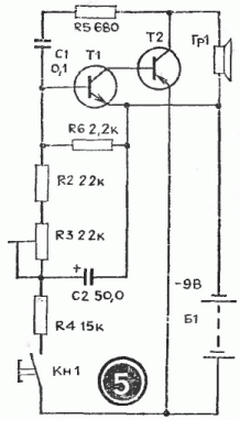
In this article, we present several devices based on one circuit - an asymmetric multivibrator based on transistors of different conductivity.
Using this circuit as a non-contact device" you can assemble a device with a flashing light light bulb(see Fig. 1) and apply it for various purposes. For example, install on a bicycle to power a turn lamp or in a beacon model, signal light, on a car or ship model as a flashing light.

The load of an asymmetric multivibrator assembled on transistors T1, T2 is a light bulb L1. The pulse repetition frequency is determined by the value of the capacitance of the capacitor C1 and resistors R1, R2. Resistor R1 limits the maximum flash frequency, and resistor R2 can smoothly change their frequency. You need to start work with maximum frequency, which corresponds to the upper position of the slider of the resistor R2 according to the diagram.
Please note that the device is powered by a 3336L battery, which gives 3.5 V under load, and the L1 light bulb is used for a voltage of only 2.5 V. Will it burn out? Not! The duration of its glow is very short, and the thread does not have time to overheat. If the transistors have a high gain, then instead of a 2.5 V x 0.068 A light bulb, you can use a 3.5 V x 0.16 A light bulb. MP35-MP38 type transistors are suitable as transistor T1, and MP39-MP42 type T2.
If you install a loudspeaker in the same circuit instead of a light bulb, you will get another device - an electronic metronome. It is used in teaching music, for timing during physical experiments and for photo printing.
If you change the circuit a little - reduce the capacitance of the capacitor C1 and introduce a resistor R3, then the duration of the generator pulse will increase. The sound will intensify (Fig. 2).

This device can act as a home bell, sound signal model or children's pedal car. (In the latter case, the voltage must be increased to 9 V.) And it can also be used to teach Morse code. Only then, instead of the Kn1 button, you need to put a telegraph key. The tone of the sound is selected by the capacitor C1 and the resistor R2. The more R3, the louder sound generator. However, if its value is more than one kiloohm, then oscillations in the generator may not occur.
The generator uses the same transistors as in the previous circuit, and headphones or a head with a coil resistance of 5 to 65 ohms are used as a loudspeaker.
Single ended multivibrator on transistors of different conductivity has an interesting property: during operation, both transistors are either open or locked at the same time. The current drawn by the disabled transistors is very small. This allows you to create economical indicators of changes in non-electrical quantities, such as indicators of humidity. A schematic diagram of such an indicator is shown in Figure 3.

As you can see from the diagram, the generator is constantly connected to the power source, but does not work, since both transistors are locked. Reduces current consumption and resistor R4. A humidity sensor is connected to sockets G1, G2 - two thin tinned wires 1.5 cm long. They are sewn to the fabric at a distance of 3-5 mm from each other. The resistance of the dry sensor is high. When wet, it falls off. The transistors open, the generator starts to work To reduce the volume, it is necessary to reduce the supply voltage or the value of the resistor R3. Such a moisture indicator can be used in the care of newborns.
If you expand the circuit a little, then the humidity indicator simultaneously with the sound signal will give a light signal - the light bulb L1 will start to light up. In this case, as can be seen from the diagram (Fig. 4), two asymmetric multivibrators are installed in the generator on transistors of different conductivity. One is assembled on transistors T1, T2 and is controlled by a humidity sensor connected to sockets G1, G2. The load of this multivibrator is lamp L1. The voltage from the collector T2 controls the operation of the second multivibrator, assembled on transistors T3, T4. It works as an audio frequency generator, and loudspeaker Gr1 is turned on at its output. If there is no need for an audible signal, then the second multivibrator can be disabled.

The transistors, lamp and loudspeaker in this moisture indicator are the same as in previous devices.
Interesting devices can be built using the dependence of the frequency of an asymmetric multivibrator on transistors of different conductivity on the base current of the transistor T1. For example, a generator that imitates the sound of a siren. Such a device can be installed on the ambulance model, fire engine, rescue boat.
The schematic diagram of the device is shown in Figure 5.
In the initial position, the Kn1 button is open. The transistors are off. The generator is not working. When the button is closed through resistor R4, capacitor C2 is charged. The transistors open and the multivibrator starts to work. As the capacitor C2 charges, the base current of the transistor T1 increases and the frequency of the multivibrator increases. When the button is opened, everything is repeated in reverse order. The sound of a siren is simulated when the button is periodically closed and opened. The rate of rise and fall of sound is selected by resistor R4 and capacitor C2. The tone of the siren is set by the resistor R3, and the volume of the sound is set by the selection of the resistor R5. Transistors and loudspeaker are selected the same as in previous devices.
Given that transistors of different conductivity are used in this multivibrator, you can use it as a device for testing transistors by replacing them. A schematic diagram of such a device is shown in Figure 6. The circuit is taken as a basis sound generator, but a generator of light pulses can be used with equal success.

Initially, by closing the Kn1 button, check the operability of the device. Depending on the type of conductivity, connect the transistor under test to sockets G1 - G3 or G4-G6. In this case, use the switch P1 or P2. If there is a sound in the loudspeaker when the button is pressed, then the transistor is working.
As switches P1 and P2, you can take toggle switches with two contacts for switching. The figure shows the switches in the "Control" position. The device is powered by a 3336L battery.