Now, more than ever, the number of gadgets per person has reached its maximum value.
Phones, tablets, laptops, miscellaneous wireless headsets- all this abundance of equipment has a power source and, accordingly, a charger for it.
The phone does not charge from the charger - what to do?
Often they carry charges with them in a bag or pocket, and so that they take up a minimum of space, their cords are twisted with a kink and a stretch.
This, in turn, leads to a wire breakage that is almost imperceptible to the eye and charging inoperability. Just break in cord- this is the most common failure in these types of devices, and, frankly, it is a pity to throw it away because of this.
Yes, you can, of course, buy a new one and not suffer, but if the device is non-standard, for example, an old model phone, then it is not always possible to find such a charger. And at the "flea market" you can slip a block with the same problem, and no one needs extra spending.
Therefore, the repair charger- a useful and worthwhile business.
How to fix a charger for a phone, smartphone, tablet with your own hands
Below, this article will describe a simple and no-requiring special equipment repair method that will give your charger a second life.
In the photo - charging with a problem in the cord.
It is not always visible to the naked eye. It can hide under the thickness of the main (top) insulation and remains almost invisible.
But, as practice shows, a fracture occurs most often near the entrance to the block or at the base of the plug.
To find the place of the break, just connect the included charger to the phone and move the cord in a suspicious place.
As soon as you see that the charge has “started” for a moment, then there is a break in the place where you were moving at that moment.
In this case, after looking closely, the kink and break were visible even without stirring. It just turned out at the entrance to the power supply.

The main problem in the repair of such blocks is that it is not collapsible. Therefore, to get to the electronic board, you need to be careful and some effort.
Using a screwdriver and a knife, you need to pry the base of the back cover and remove it.

Pry off at the point where the cord enters the device. If the entrance is too tight, you can cut the rubber band slightly.

This must be done carefully so as not to cut the wire at all.
Podkovyrnuv screwdriver, trying to lift the cover up.

It may happen that it will crack in half, but more often, as in this case, the cover came off completely, without damage.

It was even seen that it has latches, and in the case of the charger there are recesses for them.
This means that it is possible to put the cover back into place after repair without using glue.
When the cover is removed, you need to pull the printed circuit board out of the case. Since it "sits" tightly, a screwdriver will help to get it. Having rested the screwdriver blade on the case and hooking one of the soldering points with its end, we pull the board out.


The device of the case is such that when the board is inserted inside, its input contacts are connected to the clamps of the power plug pins. Therefore, when installing the board back into the case, you need to take this moment into account.
The photo below shows the board with all its "insides". The wires are soldered on the bottom.

View from the opposite side.

But in the photo there are tracks for input contacts.

The wire will have to be cut below the point where the damage is located. But it is very important to remember which wire is “+” and which is “-”. In some cases, the wires have a matching color, red is the positive and black is the negative.
With color marking, you can safely cut off, and then simply solder the wires, observing the polarity.
In our case, the wires are of the same color, but since the cord is flat, you can trace which side of the cord the wire goes to minus, and which side to plus. Mark, well, and then cut.


Without losing the label, strip and tin the wires on the cord.

Solder them one by one to the board, observing the polarity.


On the printed circuit board at the place of soldering there is usually a polarity marking.

So that the cord at the output does not hang out, we wind it around entrance part black tape bandage. The thickness of the bandage should be such that it enters the slot for the wire and locks into it.


Before installing the cover, check the operation of the device. We turn it on and connect it to the phone. If the phone is this moment not with you, use a DC voltmeter.
Since the internal contact in the socket has a very thin tube, and the probe of the device does not go into it, you can use a piece of thin copper wire to check.

Having inserted it into the tube of the internal contact, we connect the probes of the measuring device to it and the outer terminal of the plug.
The voltmeter shows that voltage is present, which means that the breakdown has been fixed.

Now snap the back cover.

We connect the phone and enjoy the results of the work done.

It turned out that within a month two ordinary Chinese chargers failed. Moreover, no symptoms and hints of the difficult work of the exercises were observed. Just at one point, the phone stopped charging.
And although such chargers are not that expensive, however, there was an interesting desire to find the reason why they stopped working after a short period of time.
cheap Chinese chargers non-separable, as they come in a cast case. And if you need to get to the device board, then the case has to be cut or sawn. The most convenient and neat disassembly option is sawing part of the body. Therefore, we take a hacksaw for metal and saw off the upper part imitating the lid in a circle.


Then we remove the board from the case. We do everything carefully so as not to break off the details and not damage the tracks.


Now we produce visual inspection boards on both sides to detect traces and exposed parts high temperature due to a short circuit or work of the part with an overload.
As a rule, in places of strong heating and burnt parts, traces of soot are visible and the color of the varnish differs from the general color. Electrolytic capacitors (barrels) at the top may be swollen.


If no visible violations were found on the board, then most likely the charging circuit is "live" and in this case it is necessary to pay attention to power supply unit, which is a weak point.
The fact is that in order to reduce the cost and automate the assembly of the charger, the manufacturer simplified the supply of voltage to its input and abandoned the wires connecting the input of the board to the metal rods (plug) that connect the charging to the network.
Contact pads are etched on the board, and the board itself is clamped between spring-loaded clamps and metal rods. For current collection, the board is pressed with its contact pads to the latches and is in a clamped position between the latches and metal rods.
Greetings radio amateurs!!! Going through old boards, I came across a couple of switching power supplies from mobile phones and I wanted to restore them and at the same time tell you about their most frequent breakdowns and eliminate shortcomings. The photo shows two universal schemes for such charges, which are most often found:

In my case, the board was similar to the first circuit, but without the LED at the output, which only plays the role of an indicator of the presence of voltage at the output of the block. First of all, you need to deal with the breakdown, below in the photo I outline the details that most often fail:

And we will check all the necessary details using a conventional DT9208A multimeter. It has everything you need for this. The continuity mode of diodes and transistor junctions, as well as an ohmmeter and a capacitor capacitance meter up to 200 microfarads. This set of functions is more than enough.

When checking radio components, you need to know the base of all parts of transistors and diodes, especially:


Now we are fully prepared for inspection and repair impulse block Let's start checking the unit for visible damage, in my case there were two burnt resistors with cracks on the case. I did not reveal more obvious shortcomings, in other power supplies I met swollen capacitors, which also need to be paid attention to first of all !!! Some details can be checked without desoldering, but if in doubt, it is better to desolder and check separately from the circuit. Be careful when soldering so as not to damage the tracks. It is convenient to use a third hand during the soldering process:

After checking and replacing all faulty parts, do the first switch-on through a light bulb, I made a special stand for this:

We turn on the charger through the light bulb, if everything works, then we twist it into the case and rejoice at the work done, if it does not work, we look for other shortcomings, and after soldering, do not forget to wash off the flux, for example, with alcohol. If all else fails and the nerves are on the line, throw away the board or unsolder it and take away the living parts as a reserve. Good mood everyone. I also suggest watching the video.
I wonder what the Siemens charger (power supply) consists of and whether it is possible to fix it yourself in case of a breakdown.
First, the block must be disassembled. Judging by the seams on the case, this block is not intended for disassembly, therefore, the thing is disposable and you can not pin high hopes in case of a breakdown.

I had to literally unravel the case of the charger, it consists of two tightly glued parts.

Inside is a primitive board and a few details. It is interesting that the board is not soldered to the 220v plug, but is attached to it using a pair of contacts. In rare cases, these contacts can oxidize and lose contact, making you think the block is broken. But the thickness of the wires going to the connector on mobile phone, pleasantly pleased, you don’t often see a normal wire in disposable devices, usually it’s so thin that it’s scary to even touch it).
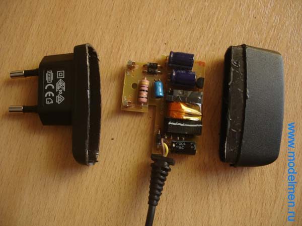
There were several parts on the back of the board, the circuit turned out to be not so simple, but still it is not so complicated as not to fix it yourself.

Below in the photo are the contacts of the inside of the case.

There is no step-down transformer in the charger circuit, its role is played by conventional resistor. Then, as usual, a couple of rectifying diodes, a couple of capacitors for rectifying the current, then a choke and finally a zener diode with a capacitor complete the chain and output a reduced voltage to a wire with a connector to a mobile phone.

There are only two pins in the connector.

A mobile phone or other device that uses a charger to charge its battery. The main reasons why the charger may fail are the following:
Wire break;
Failure of the charger unit;
Violation of the contact connection of the wire with the plug or charger unit.
Very often, the reason for the failure of the charger is a wire break or a violation of the contact of the wire with the structural elements of the charger - the plug and the block. In this case, you can repair the charger yourself. Consider the principle of eliminating damage to the charger wire on specific example mobile charger repair Nokia phone(with thin plug).
To repair the charger, we need:
Multimeter;
Soldering iron and everything you need for soldering;

If the device shows a voltage value, then this indicates that the charger unit and the wire are not damaged. In this case, the device showed 7 volts - this is the nominal output voltage this charger. At this stage, we can conclude that the memory does not work due to a violation of the contact of the conductors at the point of their attachment to the plug. You can verify this by ringing the plug with the device.
To do this, which come from the plug, insert a thin wire into the inside of the plug (this is necessary for contact with the inner contact part of the plug).
We take a multimeter and select the dialing mode. With one probe we touch one of the stripped conductors, and with the other, first to the outer contact part of the plug, and then to the inserted wire. If the device showed contact (presence sound signal), this indicates that the contact between this wire and the plug is not broken.


We rearrange the probe of the device to another stripped conductor, with the other we alternately touch the outer part of the plug, and then the wire. If, when touching both contact parts of the plug, the device did not emit a signal, then there is no contact. That is, one of the wires is torn off from the plug.
In this case, there are two ways: you can purchase a new plug, or you can repair the old one. The first way is easier and more reliable. A new plug can be purchased from mobile phone repair shops or the radio market. You may have an old charger with an intact plug.
In this case, it is enough to solder a new plug to the charger, while observing the polarity. How to check the correct connection of wires (polarity)? As a rule, each cord has a . If it does not match, then you need to make sure that the wires are connected correctly.
To do this, plug the charger into a power outlet and the new plug into your mobile phone. Connect the plug wires to the charger cord. If the charging went, then you connected the conductors correctly. If the phone does not charge, swap the conductors. The check must be carried out in any case, even if the color coding of the connected cords is the same, as there may be discrepancies in the marking of the cords.
The next step is connecting two cords. If you have heat shrink tubing, then before soldering, put a part of it on one of the cords to be soldered. Solder the conductors, observing the polarity. Insulate both wires with insulating tape, put on heat shrink tubing. Check the functionality of the charger.
If you do not have the opportunity to purchase a new plug, but you still want to reanimate the charger, then the second way to repair the damage is suitable for you - repairing the plug.
We remove the rubber (plastic) coating from the plug with a knife. In this case, be careful, do not rush, as you can damage the plug itself.


The next step is to solder the charging cord to the plug.

Check the performance of the charger. If everything is normal, we isolate the conductors, and put a heat shrink tube on the plug. The charger is ready for use.

We considered the case of contact failure at the point of connection of the cord to the plug. There may also be another reason. Let's consider one more case.
You cut the wire, checked for voltage at the output of the charger, it is missing. We cut the wire near the charger, stepping back from the charger unit 7-10 cm. We clean the wire that comes out of the charger unit and check for voltage at the output. The presence of voltage at the output indicates that the memory is working properly. We call the plug according to the above method. In this case, there is no contact failure.
The continuity of the charging cord showed that one of the conductors was broken. No visual damage is visible. The best option is to purchase a new wire. Then solder it to the plug and charger unit, observing the polarity.
In order not to be mistaken (especially if the wires have the same color coding) before soldering the wires, connect them and plug the charger plug into the phone. If charging has started, connect the conductors by soldering. Insulate the wires at the soldering point and put on a heat shrink tube (it must be put on the wire before soldering). The damage has been repaired.
If the wire is intact, the contact connection of the plug is not broken, then the charger unit is damaged or one of the wires inside the unit is torn off.
Unscrew the charger block and look at the wire connections. If all the wires are connected normally, then the memory unit itself is damaged.
If your charger unit is damaged, then, without having skills in the field of electrical engineering, you will not be able to find the cause of its failure, much less fix it yourself. Repairing a charger at a specialized service will cost you more than a new charger.