Today we have useful homemade for connoisseurs of good sound: high quality tube amplifier handmade
Hello!
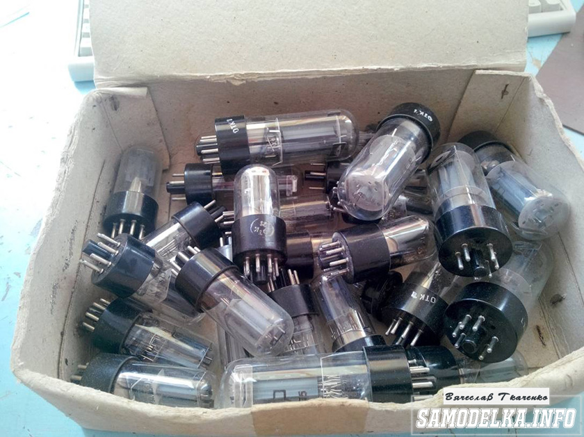
I decided to assemble a push-pull tube amplifier (my hands itch very much) from what I had accumulated over a long for a long time details: case, lamps, panels to them, transformers and so on.
I must say that I got all this stuff for free (tobish free of charge) and the cost of my new project will be 0.00 hryvnia, and if I need to buy something in small things, I’ll buy it for rubles (since I started my project in Ukraine, and I’ll finish already in Russia).
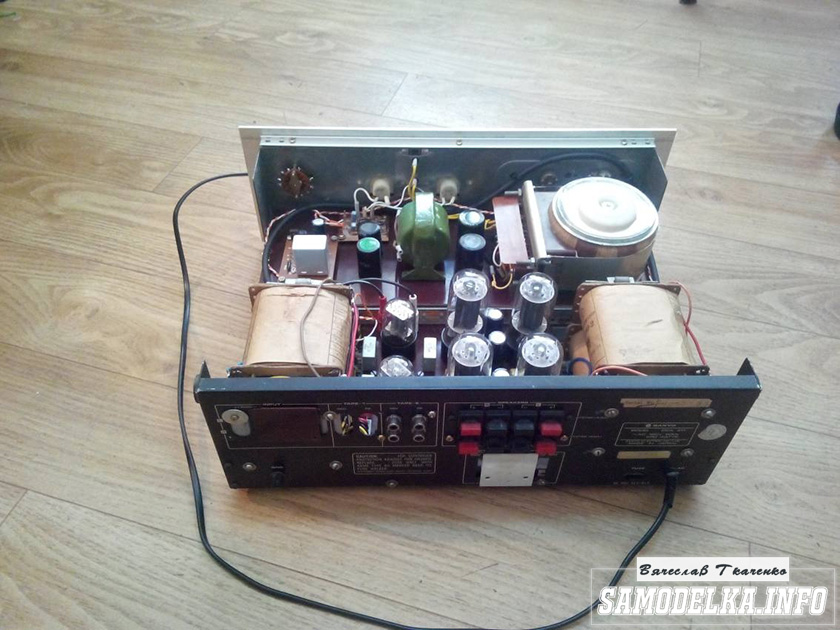
I'll start with the body.
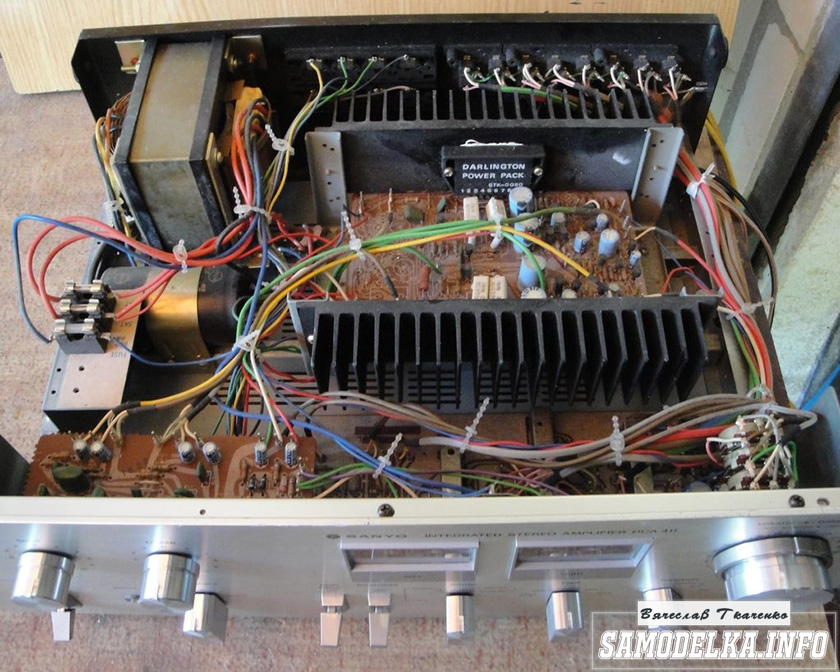
Once upon a time it was, apparently, a good SANYO DCA 411 amplifier.
But I didn’t have a chance to listen to it, because I got it in a terrible dirty and non-working form, it was dug up to the point of being impossible and the burnt 110 V networker (Japanese, probably) smoked all the insides. Instead of native microcircuits of the final stage, some snot from Soviet transistors (this is a photo from the Internet of a good copy). In short, I gutted it all, and began to think. So, I didn’t come up with anything better than to shove a lampovik there (there is quite a lot of space there).
Decision is made. Now we need to decide on the scheme and details. I have enough lamps 6p3s and 6n9s.

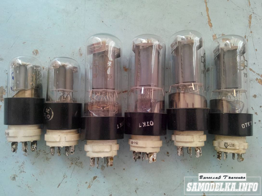
Due to the fact that I already assembled a single-cycle 6p3s, I wanted more power and, after rummaging through the Internet, I chose this 6p3s push-pull amplifier circuit.
Diagram of a homemade tube amplifier (ULF)
The scheme is taken from the site heavil.ru
I must say that the scheme is probably not the best, but in view of its relative simplicity and availability of parts, I decided to dwell on it. Output transformer (an important figure in the plot).
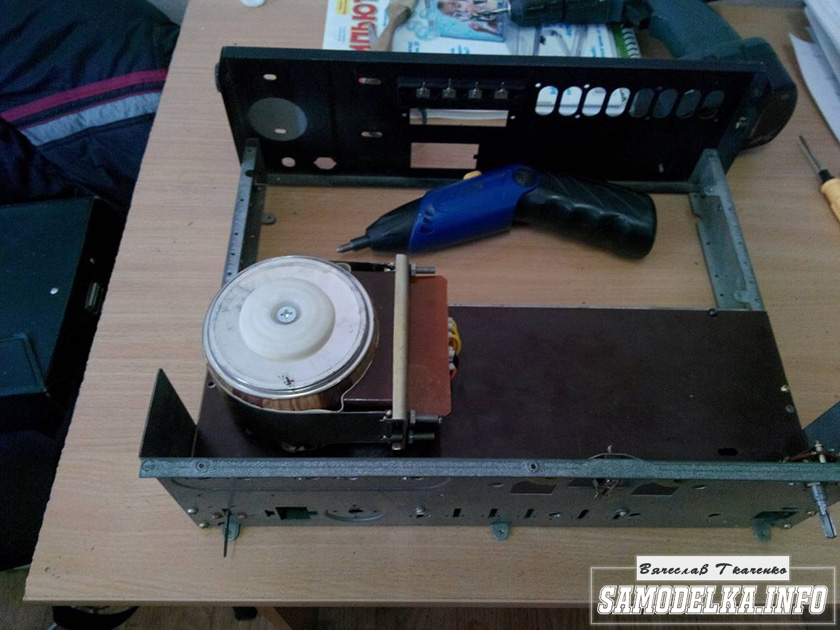
It was decided to use the "legendary" TC-180 as output transformers. Do not throw stones right away (save them until the end of the article :)) I myself have deep doubts about such a decision, but given my desire not to spend a single penny on this project, I will continue.
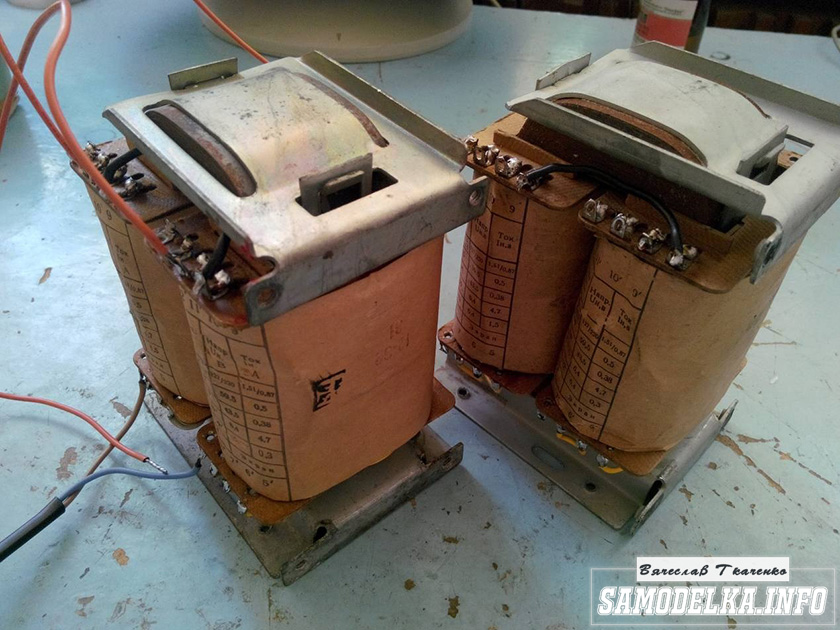
I connected the trance conclusions for my case like this.
(8)—(7)(6)—(5)(2)—(1)(1′)—(2′)(5′)—(6′)(7′)—(8′) primary
(10)—(9)(9′)—(10′) secondary
anode voltage is applied to the connection of terminals 1 and 1', 8 and 8' to the anodes of the lamps.
10 and 10′ per speaker. (I did not come up with this myself, I found it on the Internet). To dispel the fog of pessimism, I decided to check the frequency response of the transformer by eye. To do this, I assembled such a stand in haste.

In the photo, the GZ-102 generator, the BEAG APT-100 amplifier (100V-100W), the C1-65 oscilloscope, the load equivalent of 4 ohms (100W), and the transformer itself. By the way, the site has.
I set 1000 Hz with a swing of 80 (approximately) volts and fix the voltage on the oscilloscope screen (about 2 V). Then I increase the frequency and wait for the voltage on the secondary of the trance to begin to drop. I do the same in the direction of decreasing the frequency.
The result, I must say, pleased me. The frequency response is almost linear in the range from 30 Hz to 16 kHz, well, I thought it would be much worse. By the way, the BEAG APT-100 amplifier has a step-up transformer at the output and its frequency response may not be ideal either.
Now you can collect everything to the heap in the case with a clear conscience. There is an idea to make the installation and layout inside in the best traditions of the so-called modding (minimum wires in sight) and it would not be bad to make the backlight with LEDs as in industrial copies.
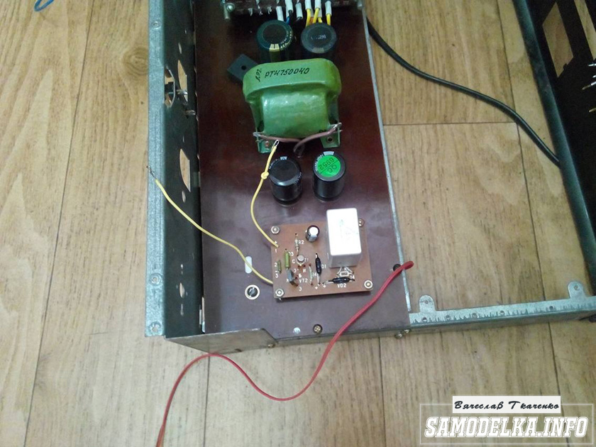
Power supply for a homemade tube amplifier.
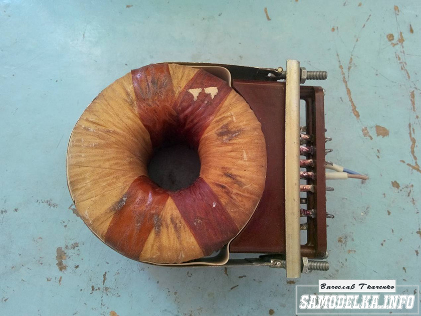
I will start the assembly with at the same time I will describe it. The heart of the power supply (and the entire amplifier, probably) will be the TST-143 toroidal transformer, which I at one time (4 years ago) tore with meat from some kind of tube generator right at the time it was being taken to a landfill. Unfortunately, I didn’t manage to do anything more. L, it’s a pity for such a generator, or maybe it was also a worker or it was possible to fix it ... Okay, I digress. Here he is my enforcer.

Of course, I found a diagram for it on the Internet.

The rectifier will be on a diode bridge with a filter on the inductor for anode power. And 12 volts to power the backlight and anode voltage. Throttle I have.
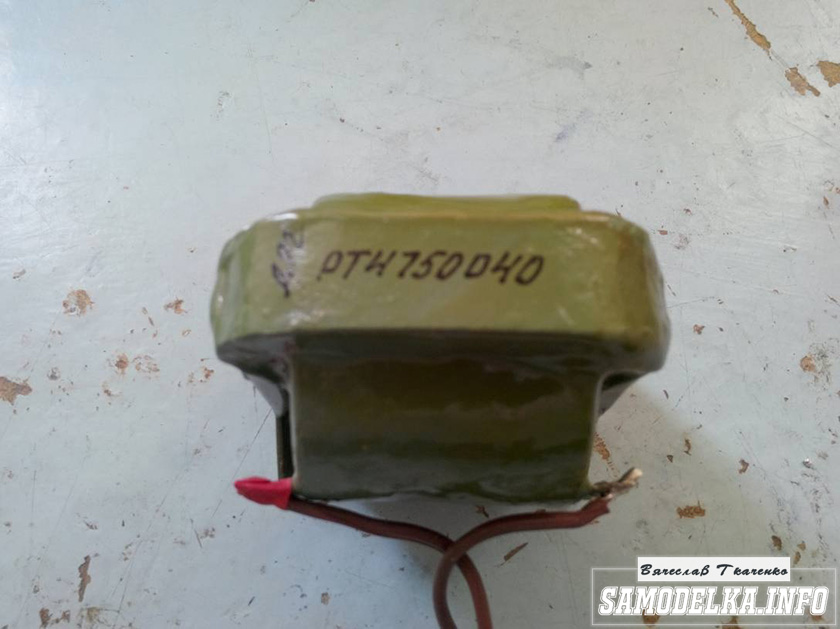
Its inductance was 5 henries (according to the device), which is quite enough for good filtering. And the diode bridge was found like this.

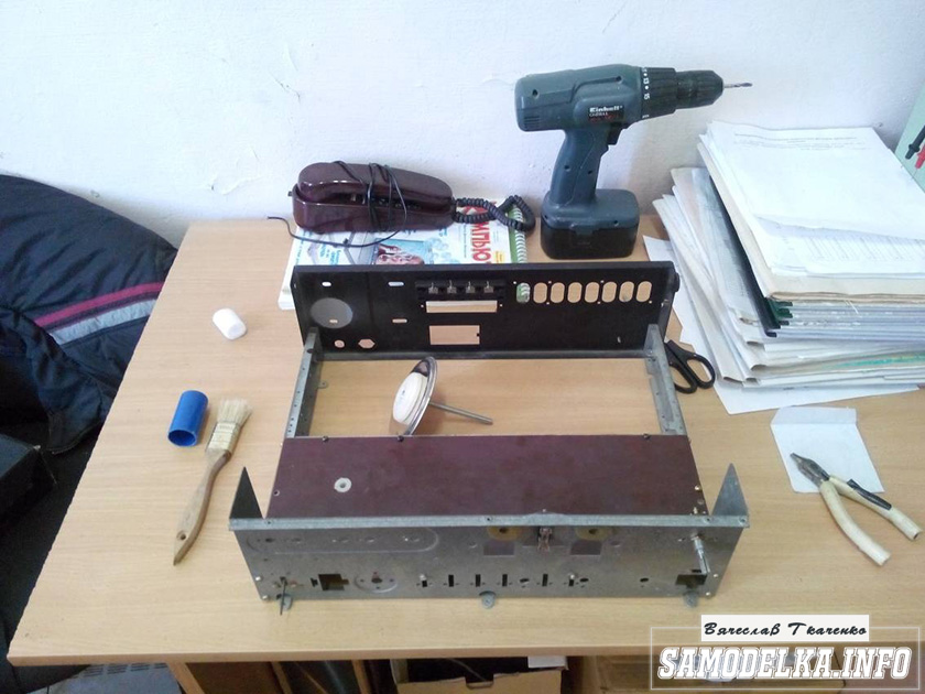
Its name is BR1010. (10 amps 1000 volts). I'm starting to cut out the amplifier. I think it will be something like this.

I mark and cut holes in the textolite for panels for light bulbs.


It turns out not bad :) so far I like everything.

And so, and so. drilling sawing :)
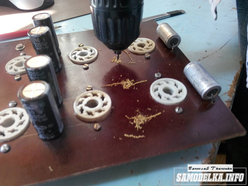
Something began to emerge.

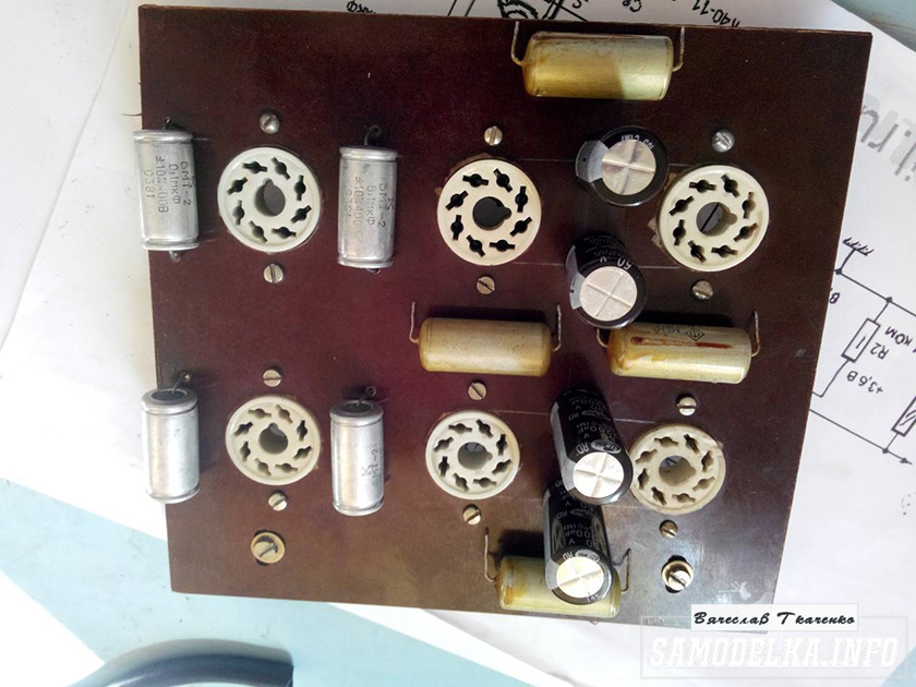
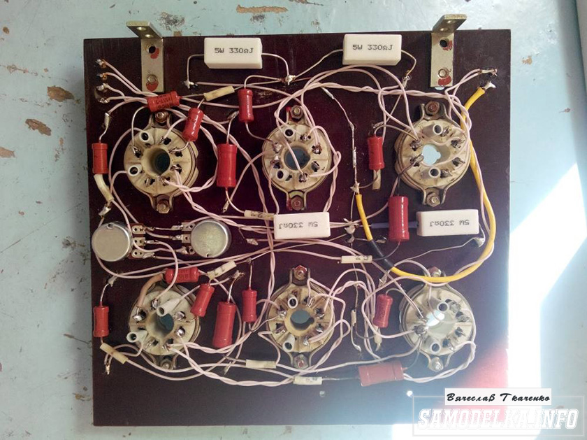
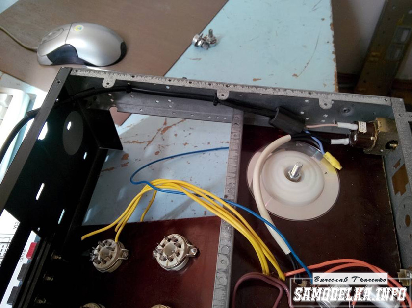
I found a fluoroplastic wire in old stocks and immediately all the alternatives and compromises regarding the wire for installation disappeared without a trace :).


This is how the installation turned out. Everything is as if “kosher” the incandescences are intertwined, the earth is at one, practically, point. Should work.
It's time to fence food. After checking and checking all the output windings of the trance, I soldered all the necessary wires to it, and began to install it according to the accepted plan.

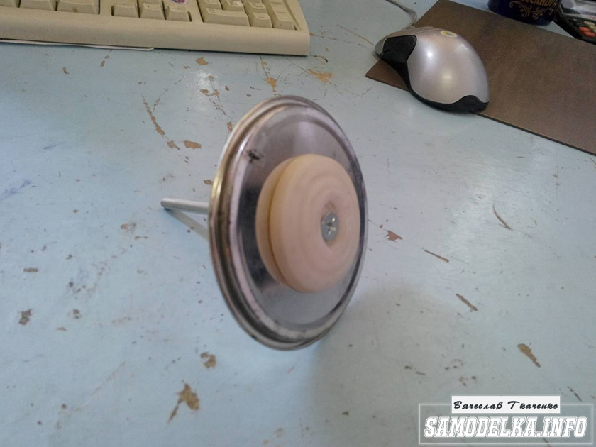
As you know, in our not easy anywhere without materials at hand: the container from the Kinder Surprise came in handy.

And a Nescafe lid and an old CD


I ripped out TV and monitor boards. All capacities are at least 400 volts (I know that I need more, but I don’t want to buy).

I shunt the bridge with containers (which ones were at hand, I’ll probably change them later)

It turns out a bit too much, but oh well, it will sag under load :)
I use the regular power switch from the amplifier (clear and soft).

Done with this. Well done :)
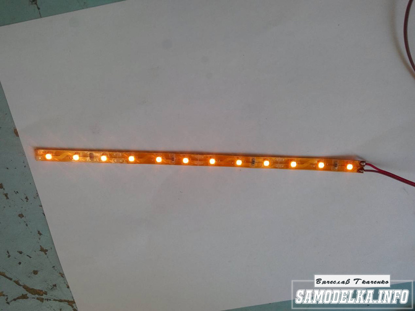
Illumination for the body of the tube amplifier.
To implement the backlight, an LED strip was purchased.
And installed as follows in the case.
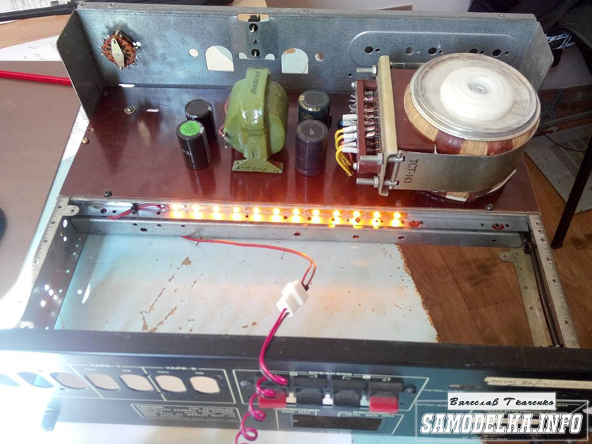

Now the glow of the amplifier will be visible in the daytime. To power the backlight, I will make a separate rectifier with a stabilizer on some kind of KRKEN-like microcircuit (which I can find in the trash), from which I plan to power the anode voltage supply delay circuit.
Delay relay.
Digging through the bins of my homeland, I found just such a completely untouched thing.

This is a radio time relay kit for a photo enlarger.


We collect, we check, we try on.
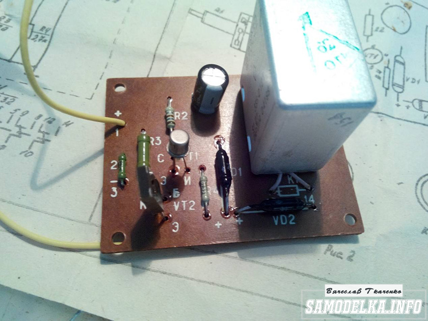

The response time was set to about 40 seconds, and variable resistor replaced with a permanent one. The case is coming to an end. It remains to put everything together, put the muzzle, indicators and regulators.
Regulators (input variables)
They say that the sound quality can greatly depend on them. In short, I put these

Dual 100 kOhm. since I have two of them, I decided to parallelize the conclusions, thereby obtaining 50 kOhm and increased resistance to wheezing :)
Indicators.
I used standard indicators, with standard illumination

The connection diagram was mercilessly bitten by me from the native board and is also involved.

Here's what I ended up with.


When checking the power, the amplifier showed a voltage at the output of 10 volts of an undistorted sinusoid with a frequency of 1000 Hz to a load of 4 ohms (25 watts) equally across the channels, which pleased :)
When listening, the sound was crystal clear without background and dust, as they say, but too monitor, or what? nice but flat.
I naively thought that he would play without timbres, but ...
When using the software equalizer, we managed to get a very beautiful sound that everyone liked. Thank you all very much!!!
Consider an example of constructing and calculating one of the power amplifier circuits audio frequencies(abbreviated - UMZCH)Operational amplifiers (op-amps) are a good thing! The range is extensive, the characteristics are excellent, the price is comparable to transistors, but the trouble is that the supply voltage in most cases is ± 15 V, which limits output voltage approximately at the level of ±10 V, the output resistance is also quite large - on the order of several kOhm. This does not allow you to use the op amp directly to drive loudspeakers. But we still have a "Reserve of the main command" - power transistors! Only now, in order to obtain high power at the output of the UMZCH, they need quite high voltage nutrition. So what? We make a preliminary stage on an op-amp with a stabilized power supply of ± 15 V, and a transistor output - with a power supply with an unstabilized voltage of the magnitude that only the output transistors will allow us to. Why with unstabilized? There are several reasons: the difficulty of implementing a high-voltage stabilizer of sufficient power with acceptable characteristics of efficiency and quality; also by the fact that the interference and distortion introduced by the power supply in powerful cascades are practically much less significant than in preliminary cascades due to the difference in the signal-to-noise ratio.
Let's go straight to the diagram. The UMZCH circuit is chosen as two-band, which allows the use of an op-amp with rather low frequency response. The whole circuit is actually an inverting amplifier with negative feedback (NFB) and a gain equal to R2/R1. The gain factor should not be chosen more than 10, which in fact, with an input signal of ±10 V, gives a signal of ±100 V at the output. The frequency band of this UMZCH is practically limited only by the frequency characteristics of the output stage. It should also be noted the good stability of the "zero", due to the use of an op-amp and optimal frequency characteristics.
Schematic diagram of UMZCH
Description and calculation of the scheme
In order for the frequency band in the amplifier not to be limited by the characteristics of the op-amp, the input signal is applied to the low-frequency and high-frequency paths. The buildup signal is applied to the emitters of transistors VT1 and VT2, which form cascode pairs VT1-VT3 and VT2-VT4 on transistors of the opposite structure.
First, let's set the collector currents of transistors VT1—VT4 10 mA. As a result, the current through the resistors R12, R13 should be 20 mA. As VD1 and VD2 we use LEDs with a voltage drop of 1.6 V (most red LEDs). These LEDs can be used simultaneously as power-on indicators. It is also possible to replace these LEDs with zener diodes or stabistors with the appropriate stabilization voltage, but then we lose the function of indicating the power on of the amplifier.
Considering the voltage drop across VD1 and VD2, equal to 1.6 V on each and subtracting the base-emitter voltages on the transistors VT3 and VT4 we get the voltage across the resistors R12 and R13 1 V each. From here: we divide the voltage drop across the resistors R12 and R13(1 V each) for a current of 20 mA set through them, we get R12=R13=1V / 20mA = 50Ω
. The nearest standard resistance value is 51 ohms.
In the absence of a signal, the current through the resistors R5=R6 is approximately 0.6 V / R6. It is by this value that the current through the resistors R9, R10 must exceed the specified collector current of the transistors VT1, VT2(by 10 mA).
For the most effective use current sources on transistors VT3, VT4 it is necessary that their collector currents change from an average value of 10 mA to ± 10 mA, i.e. so that the range of their change is from 0 to 20 mA. Based on this, we determine the resistance of the resistors R5=R6= 10 V / 10 mA = 1 kΩ
(coincides with the standard value). From here we get the current through the resistors R5, R6 at rest 0.6 V / 1 kΩ = 0.6 mA, and through resistors R9, R10- (10 + 0.6) \u003d 10.6 mA. Therefore, R9=R10=15 V / 10.6 mA = 1.4 kOhm. We select the standard nominal value of 1.3 kOhm.
The calculation of the interface of the op amp with the final stage is completed. Now let's move on to the output transistors.
Current protection of output transistors is provided by transistors VT5, VT6, whose base circuits are connected to current sensors R18, R19. If the voltage at the base of the transistor VT5 or VT6 exceeds 0.6 V ( UBE≈ 0.6 V), the corresponding transistor will open and shunt the base-emitter junction of the corresponding output transistor VT7 or VT8. The output current will be:
Ilim \u003d UBE / R18 - ((Up - Uout).R16) / (R14.R18)
During operation, this current increases along with the load current when the output voltage approaches the supply voltage. Up. On condition R14.R18/R16 = Rn
, limiting current for any positive values Uout for transistor VT7 or negative for VT8 there will be more load current by the value ΔI=UBE/R18-Up/Rn
. Given the value ΔI=(0.1...0.2)Imax
and knowing the values Up and Rn you can calculate the resistance of a resistor R18 based on the previous formula. the value Rn should be set to the minimum possible. Next, choose the resistance of the resistor R16 in the range from 200 to 800 ohms and determine the resistance R14=Rн.R16/R18
. Because the scheme is symmetrical, then: R14=R15
, R16=R17
, R18=R19
.
Maximum power dissipated by each of the transistors VT7, VT8 in operating mode at LF with the selected protection method is: Pmax=(U2BE.R14)/(4.R18.R16)=0.25Rn(UBE/R18)2
.
Note that in emergency mode, i.e. in the event of a short circuit of the amplifier output to ground, the power dissipated by the output transistors will not exceed (0.1...0.2)Imax.Up
, and when the amplifier output is shorted to the power source, the output transistors will generally close. Moreover, it comes at a time when Ilimit=0
, i.e. when Uout=Up-UBE.Rn/R18
. In real conditions VT7 locked at Uout less than minus (2...4) V, VT8- at Uout more than +(2...4) V. Compared with the protection circuit without the use of dividers R14-R17 The applied circuit has obvious advantages: the maximum power dissipation when the output is shorted to ground is 6-11 times less, and when it is shorted to the power source, it is even half as much.
Due to the drop in the amplitude-frequency characteristic (AFC) of the op-amp, signal distortion increases with increasing frequency. Therefore, it is necessary to take measures to ensure that the RF path starts working before signal distortions in the low-frequency path made on the OS become noticeable. To do this, the cutoff frequency of the low-pass filter (LPF) at the input of the op-amp formed by R3 and C2 should be chosen around 10 kHz, i.e. R3\u003d 16 kOhm, C2\u003d 1000 pF. High pass filter cutoff frequency (HPF) R4C1 should be chosen no higher than 1 kHz, i.e. R4\u003d 20 kOhm, C1\u003d 0.01 uF. RF open-loop gain is set by resistors R7, R8. The gain must be set together with the choice of capacitance C3 = C4, so that with a closed circuit of the feedback of the entire amplifier, the desired type of transients is achieved. In principle, in this circuit it is possible to achieve a THD value of 0.005%.
For the op-amp, a standard frequency correction is sufficient. When the amplifier is excited at high frequencies, it can be suppressed by introducing base resistor transistor circuits. It may be necessary, in the case of an inductive nature of the load, to connect a corrective RC circuit, as well as shunt R2 a small capacitor connected in series with a resistor of 0.1 R2. The output transistors can be composite, which allows you to achieve good energy and quality indicators. And let me remind you - you should not forget about the power of the resistors. First, it is determined by the current through the resistor - P=I2.R
, and secondly, the maximum allowable voltage on the resistor.
Literature:
1. Titze U., Shenk K. Semiconductor circuitry. — M.: Mir 1982
2. To help the radio amateur: Collection. Issue. 89. - M.: DOSAAF, 1985
3. Shilo V. L. Linear integrated circuits. - M .: Soviet radio, 1979
This article is about how to assemble an amplifier for 3000 rubles that combines the best qualities of these two handsome men in the photo below ...
Of course you recognize them...
More recently, I had two of the brightest representatives of the Soviet amplifier industry - the Odyssey U-010 stereo Hi-Fi of 1987 and the Brig-001 of 1983.
And two more less bright, but more common - Amfiton 202 and Elektronika 50U-017, which are also shown in the pictures below.

Plus, there were Odyssey 001, Rostov MK-105S, TDA 2004, TDA2030A, TDA2050, TDA7294 all in a typical inclusion.
Now I don't have any of that...
But there is this article in which I will tell you why. First things first, the most interesting, as a rule, at the end.
For a year in my city, I was buying more or less working Soviet amplifiers, restoring them and listening, hoping to find one that would satisfy me with sound quality, assembly, design, and just liked it, and I describe the results of my searches in this article.
So...
- old, 75 year of manufacture, but this grandfather knocks 30GD out of the basket so much as if there were not 30 watts / 4 ohms in the passport, but all 100, seriously, I was stunned by what he does with the low-frequency, and this is perhaps the only thing that I have he liked it, but no, there is something else - he is 37 years old and he works!!! The distortion factor is 1% and it is noticeable, although the sound is not soapy - there are so many high ones that you can pull out the tweeters with such an amp, and the bass can be rather peculiar due to germanium transistors. Paired with the S30B, it definitely plays better than the budget Svens, and besides, it is a real retro in wood and with a good assembly. I liked it.

Rostov MK-105 C- this is a tape recorder, the power for the S90 is the most, it was just delivered with them, the sound is very good, and it is with these speakers, soft bass, good design, beautiful arrow indicators, but even when replacing all the capacitors, hiss remains, this is due with a long way sound signal to the power amplifier (through the input amplifier, tone block, playback amplifier), besides, the signal circuits are not shielded, but if you turn up the volume, this disadvantage is no longer audible. I liked it.
Amfiton 50U-202- probably like any amphiton of a similar model range(25U, 35U) is not suitable for high-quality sound reproduction, at least do something with it, there are no high ones, or if you unscrew it - it is distorted, instead of bass there is a rumble, and if you turn on loudness, then active filter subwoofer ready)). The device is distinguished by its simplicity and reliability, even excessive, probably many users of this amplifier have ever thought of replacing one resistor in protection in order to reduce sensitivity. It is of interest only as a case with good heatsinks for installing TDAs, for example. Didn't like it.
Electronics 50U-017. Electronics, as the flagship of Soviet electronics, loved to make watches and calculators, so they would do it further ... I have never seen such fancy circuitry, it feels like they pushed everything they could into it, how else did they put the processor)), but somehow positively on the sound it had no effect, noisy, incorrect due to electronic switch and the same unshielded long signal loops as in Rostov 105, the tone controls are too sharp, with an increase in power, distortions grow too much, but the loudness is unusual, as if pressing, deep and a nice indicator, but the main thing is the sound, but it is not very. Didn't like it.
TDA 2004- as long as it was...
TDA2030A- well, so-so, but on its radiator you can fry something or someone)).
TDA2050- already something, overclocked it to 50 watts / 4 ohms, withstood it, the sound is pretty good if you don’t listen carefully, because. detailing is typical microchip, i.e. soap, but I liked its soft bass tone and reliability. In my opinion, the best choice for not bothering to listen to music at no extra cost. There was an idea to make active S30 with it, I think they would work together. I liked it.
TDA7294- I will not write much, everyone knows everything, the microcircuit is very popular. I liked it because of the price / quality ratio, probably only the LM3886 is better in sound, but at least we have it twice as expensive. The detail is higher than that of the TDA2050 and the sound is colder and sharper compared to it, perhaps due to more pronounced high frequencies. Although, if you don’t find fault, then the TDA7294 is quite suitable for the S90 as an amp for listening to pop music at an RMS power of up to 50 watts, higher is no longer hi-fi ... Until I bought the Odyssey-010, it was like nothing, now I can’t perceive it well.
Before moving on to the very best, a few words about how I listened. Used to listen sound card HD Audio, bitrate from 320 and music of different styles, here are just some of the songs:
Dj Matisse & Lounge Paradise - This Love (Maroon 5 Cover);
DJ Shah feat. Nadja Nooijen - Over and Over (Original Vesrion)
Lesopoval - Ya kuplu tebe dom;
Wicked DJs - Disco Rocker (Picker Remix);
Stas Mihaylov - Koroleva;
Tritonal Ft. Cristina Soto - Forgive Me, Forget You (Triple Mash Intro)
Eva Polna - Luby menya po francuzski (Fonzarelli Chill Out Acoustic Mix);
Dire Straits - Money For Nothing (Album Version).

The speakers are my favorite S90, which I naturally finalized, the essence of the refinement, probably, should already be entered as a standard in the GOST register, but I will list the main methods of treatment once again:
- Coating seams with sealant
- Treatment of the inner surface with rubber-bitumen mastic
- Pasting the inner surface with padding polyester (ideally, of course, with felt, but I just couldn’t find it anywhere in the city, and I don’t want to cut felt boots, and I can’t do just one pair)
- Damping the midrange speaker or replacing it with a 6gdsh - by the way, I didn’t find it either, so I closed the windows of the 15gds basket with foam rubber
- Replaced the wires with thicker ones
- I painted the grilles with glossy black enamel and glued them with self-adhesive under the tree
- Laid a couple bags of cotton
- I want to put on spikes, but I don’t have time to carve everything, and I think this will be the final point of refinement, I can’t squeeze more out of them.
And now they really sound!
And now for the best.
Odyssey U-010 stereo Hi-Fi- brutal, quite a solid thing, 16 kilograms of non-ferrous metal.
In addition to its attractive appearance, it has two advantages - power and bass. If you measure the RMS power according to the RMS standard, then I squeezed out 183 watts at 4 ohms, 120 watts at 8 ohms, beast)). Probably, everyone had such a feeling when you drive our domestic and accelerate to a hundred and then slow down, because. it seems that it will fall apart now, and then get into a foreign car, give it a little gas, and it is already 60, a little more 100, but everything is comfortable and the speed is not noticeable, about the same here, I turn it to the full, so that sound wave the T-shirt stirs with bass, but the sound is not distorted, it is almost the same as when the volume knob is on the two, although the power for the speakers is already dangerous, the music does not turn into a continuous set of sounds, well, perhaps at the very maximum, I really like it.
According to the assembly about him, by the way, you can also say “bucket with nuts”. The details are horrible, the wires of the power supply and output transistors are thin, there is no shielding, soldering and textolite, to put it mildly, are not the best, while soldering the capacitors several tracks came off, I had to lay wires.
The preamplifier for a device of this level is terrible, when all the knobs are at zero we already hear a slightly different sound and only by connecting the signal directly to the PA stub we can talk about quality, although this one is interesting for such a unique thing as “frequency response balance”, discrete controls and a lot of function buttons .
Power supply - class! The transformer, although it buzzes, filled it with paraffin - it did not help, but what a powerful and tightly assembled one. Distinctive feature of this amplifier is the presence of a voltage stabilizer, in general a thing in Soviet amps is unique, as is the balance of the frequency response. The stabilizer allows you to keep a constant voltage level on the power amplifier +/- 37 Volts even at high volume. The voltage drop according to my measurements was only 0.6 volts! This largely explains the good sound quality at high powers.
The protection allows you to work not only with an 8-ohm load, but with a 4-ohm one, however, at a volume of more than half, you need to be careful, when the output is closed, the protection does not save, AND YOU DO NOT NEED TO CHECK FOR ME!, although on the other hand they fly out for some reason - then transistors of the KT502 type in the stabilizer, and a couple of KT818/819 outputs in the PA remain unbroken, strange.
Despite the shortcomings of the performance, of course, it is worth noting the sound, it is good, or rather the bass is clear, even a little rough, but deep enough. I love progressive house, tech, electro - it's perfect for such styles, which can't be said about pop and classics, it has few highs by default (the initial problem is in the timbre block), you have to turn them all the way with the handle, then the cymbals are heard well, the middle ones are so himself and in this he will clearly lose to the next.
Brig 001- a copy of 1983, the second version of the circuitry with one opamp in the power amplifier. I read somewhere that the first copies were installed on personal orders in the offices of officials of the Central Committee of the CPSU, who loved good sound and who then listened exclusively to Japanese Marants and Technics, naturally not available to ordinary citizens. However, the brig was far from accessible to everyone, since its price at that time was about 600 rubles, while the same Odyssey -010 later cost 350.
Of course, the brig is the best, the best of the Soviet ones of that time, there is a lot of controversy and discussion around it, but few improvements, which means that for some it is already not bad, but not for me. It is undeniably very reliable and stable, besides it is well built, I had a copy with military acceptance details. In general, it is not particularly maintainable due to the fact that all the main components are connected not with plugs and plugs, but with wires and soldering, however, it is not difficult to unscrew any board, but to remove it, you will have to solder. The quality of the textolite and soldering is on top. The number of electrolytic capacitors is probably even less than in all the amplifiers described earlier.
About sound. This is an amplifier for chanson. And restaurant music, which I also love, it is a great pleasure to listen to it, in general, everything with vocals and live instruments, classics, jazz. Sparkling highs, good mids, vocals and not bad lows, judging from this sequence it is easy to conclude that this is the opposite of the Odyssey 010, plus I would add to this statement that listening to the brig through the plug, bypassing the preamp, I would not say that he impressed me On the contrary, the beauty of the sound coming from the brig is largely the merit of its timbre block.
Many people like its soft bass, I personally do not, because when listening to electronic or heavier music at rated power, all this soft bass becomes a mess.
It turns out that each amplifier is good in its own way, there is no universal ...
Of course, having reviewed all the options, only the last two remain, but they are not similar, heaven and earth, double bass or cymbals, bottom or top, choose what you like. We are all different and the technique is different, someone has a hearing, someone does not, someone can listen to a Chinese receiver in the country without worrying, and someone is not satisfied with a home hi-fi system for a round sum and wants something more , people are starting to switch to tubes ... or spend a lot of money on branded sound equipment. And probably for the average listener, happiness is in the balance of price and quality, so as for the sound of Soviet amplifiers, it is not bad, after replacing the capacitors, correct wiring of the ground and shielding, adjusting the quiescent current, replacing some parts with imported ones, increasing the power of the supply transformers or replacing them toroidal...etc, so many things!
I want the bass odyssey and the vocals of the brig, combinations best qualities in one device. Is it really necessary to take and solder one to the other? What to do to a person who wants to immerse himself in the world of good sound without much hassle and expense?
I will answer - to accumulate the same collection, bring them to mind, listen again, make sure that there are no ideal Soviet amplifiers, just as there are no ideal women, get disappointed and sell everything!
And collect yourself!
And in the hardware store, you always pass with a smile past people who choose a beautiful Chinese stupid box with an unthinkable number of tulips on the back panel and a price of their salary ... when, at home, there is an amplifier that is awesome in terms of sound, simplicity and cost, capable of both performance and sound to make the Chinese receiver smoke! I propose an amplifier in which there are both high and low, in which everyone will definitely find for themselves a part of the brig and the odyssey and hear for themselves what they want, as I did!
What kind of booster is this?
This is Radio Engineering U-101?!

In general, Radio Engineering is probably just created in order to be “raped” one day ... it is beautiful, even now its ergonomics and design excite the inquisitive minds of radio amateurs who have itchy hands and only 20 watts in it - this is too little to resist. We will take it as a very convenient platform for implementing our own ideas in the field of good sound for the home.

From many different schemes, I have chosen those in this moment, in my personal opinion, they are optimal in terms of price / quality ratio, I will say right away that I did not make any changes other than those described in the original schemes, everything is done as it is. I won’t talk about the blocks themselves for a long time, I’m not a radio engineer to explain where what is happening, I’m an ordinary radio amateur, so detailed information read the links provided. By no means am I copying circuits, I do not encroach on the copyrights of people - radio engineers who have spent time and money on creating these circuits. It's a build, a build that's good enough to satisfy the average listener who doesn't want to pay big bucks for who knows what. This amp really plays!
So, let's begin.
When I nevertheless climbed under her cover ... I was horrified, the wires from the trance were charred, in the power amplifier the parts were soldered inexplicably, some were soldered with only one leg, when turned on, the rectifier diodes got very hot and stank of smoked resistors)). The indicator didn't light up. But outwardly well preserved. A beautiful copy - what I wanted to remake.
A complete dismantling began, as a result of which I left the transformer, tone block, indicator, input switch.
Photo of the insides (this is not my copy, everything is still good here).

We need it so that there is no hole on the back panel and that there is a socket for entry. The socket above which “record” is written is free and there are no tracks on the board to it, we solder a shielded speaker wire leading to the preamplifier to this socket. This will line input. We immediately close the mass with wiring to the amplifier case, for this special petals are provided on the frame, if this is not done, there will be noise.

Also, the switch board can serve as a platform for mounting the protection board, for this we take out the phono stage box, thereby freeing up space and put the speaker shutdown relay included in the protection circuit on liquid nails, and mount the board itself next to it.
For example, I managed to clamp the radiator of the output transistor of the protection circuit between the petals of the socket under the fuse.

Change electrolytic capacitors. Tidy up the wires.
Because I pulled everything out, I had to figure out which wire goes where.

If you look at the XP7 socket, the one that is inserted on the display board, then the contacts 10,11,12 go to the glow and are soldered to the corresponding terminals on the transformer.
Contacts 5-power plus, 6-power minus, 4-common are connected to the power supply of the preamplifier before the stabilizers, then it will be shown how.
Contacts 2 and 3 are connected to the outputs of the power amplifiers of the right and left channels.

To power the power amplifier, I took a toroidal transformer with two identical secondary windings of 20 volts each with a power of about 100 watts and screwed it to a metal substrate at the bottom of the amplifier case, having previously drilled a hole of the required diameter in it. Next to this trance we have a power amplifier rectifier. As a diode bridge, we take an imported KVRS 5010. We assemble a block of 6 capacitors of 4700 microfarads x 50V, 3 per shoulder and shunt with two 1 microfarad film capacitors. The scheme is standard and needs no explanation.


The preamplifier, indicator, protection and switching will work from the native trance.
On the native transformer, pin 6 is the middle point, and a voltage of 16.3 V comes out of pins 5 and 5 ”, we connect these pins with wires to the stabilizer circuit (pins 5-6-5).
And they also take power for the indicator.


To power the protection circuit, we make a separate rectifier, because. when connected to an existing preamplifier power supply, noise and low-frequency hum occur, which I could not overcome even with a 10,000 microfarad capacitor. But then another problem arose - the protection circuit operates with a voltage of about 24 Volts, which means that about 16 Volts must be removed from the transformer before the rectifier, however, when measuring the voltages of the remaining windings of the native transformer, the minimum that I found is 37 Volts between terminals 4 and 4 ', I had to and use them, because the third transformer would be too much. After the rectifier, the voltage was reduced by a chain of a 5-watt resistor by 1 kΩ and 3 D814 zener diodes connected in series. Of course, it was possible to do everything more professionally and choose a suitable stabilizer, however, everything works like that.

This protection scheme is quite popular, so I find it difficult to indicate the source, a similar scheme is in the brig001 amplifier of the very first edition. One thing I can say is that before that I had assembled two more similar circuits, but designed for bipolar power and was dissatisfied with their work, the problem was that no matter how I set up and selected the ratings of the parts, the voltage on the contacts of the relay coil did not drop to that level at which the opening of the contacts associated with the AC would occur, but here everything is simple and reliable. Turn-on delay about 2 seconds. During the preliminary check, between the common wire and the resistor R1 connected two finger-type batteries, thereby making sure that even with three volts of constant voltage, the circuit works, clicks the relay and turns off the acoustics. Switch S1 is placed on the front panel (I have it to the right of the indicator), it can also be controlled by turning off the speakers. Any VT3 transistor that is more powerful from the KT 815, KT 940 series, etc. it heats up, put it on the radiator. The board is not designed for .

preamplifier
I wanted to leave my own, I have it with a version on three microcircuits, but the SP-3 resistor with loudness exhausted all the nerves with uneven regulation and rustling, although after filling it with engine oil the situation improved, you need to understand that this is still an emergency measure, but to find one a new one is probably impossible even at the factory itself, as well as the factory itself ...
In addition, the level of noise and distortion of the native timbre block was high, I connected it, as many advise, bypassing the first microcircuit and threw it away anyway. Although as for the sound, I liked this pre, the bass is deep, there are highs and in general it sounds somehow pleasant. However, we collect real Hi-Fi and therefore we don’t need any artificially created amenities, we need a timbre block that by default does not introduce audible changes into the sound.
Once I collected it on the TDA1524 - horror, the distortion coefficient is about 0.3%, this is a lot, as I didn’t center the resistors, I picked up capacitors - anyway, the microcircuit makes changes to the sound, it will only work as an active filter for the subwoofer.
I read about before Solntsev, who, in addition to good characteristics, has the same good feedback, but did not collect, because there is a need to use a resistor with loudness, which cannot be found in the normal state, besides, the preamplifier is built on the same Soviet element base, from which I have already moved away to import.
I collected it on the LM1036 - all the same problems as with the TDA, but the distortion factor, according to some sources, is about 0.05%, this is already better, and it sounds much better, although it is cheaper than the TDA and still not that, not Hi- fi.
And then I assembled a preamplifier on three NE5532 opamps - a class, when the knobs are in the center, it’s as if there is no tone block at all - this is what I wanted and was looking for! There is a mode of linearity of the frequency response, the coefficient of harmonics for these options in the datasheet, for some reason I did not find, but there is data that 0.007%. It is bad that there is no loudness and its implementation is possible again with a special resistor. Just this tone block will go into my complete amplifier. This scheme is taken from a foreign site at this link.
I don't think there's much to explain here.

I did not find a board on the network, I had to develop it myself. The board was not created for laser-ironing technology, I make boards the old fashioned way with a marker and etch in ferric chloride.

Amplifier
But actually he, the hero of the occasion, who conquered me with his sound and cost, power amplifier

Here I will not write anything, probably no one can tell about it better than its creator, whose article can be read
From myself, I’ll just add that at a voltage of +/- 27 Volts, the rms power when a 1 kHz sine wave was applied at a 4-ohm load was 104 watts, and yet - I haven’t heard anything better yet ...
About Assembly
In the amplifier of Radio Engineering, the resistors of the tone block were soldered into the preamplifier board itself and fastened with nuts to the bar, which in turn was connected to the case. To install imported resistors in the same holes in this bar, you need to drill holes for the ledge of the resistor with a diameter of 3 mm, as in the figures. This will provide a guarantee against rotation, besides, this protrusion is formally the middle of the horseshoe of the resistor, so it is necessary to drill holes as horizontally as possible. On the reverse side, we fix the resistors with nuts.

Turning off the tone block in the preamplifier is carried out with the help of a relay, which I powered in the same place as the protection board, the tone on / off button is placed on the front panel (on my left).

After removing the main innards, I also removed the “copy inputs” and headphone jacks, leaving holes on the front panel, which is not very beautiful. In this case, Soviet non-polar capacitors such as K50-6 came in handy, wrapped with tape in one layer, which fit very well into these holes, now it looks more like buttons.

The most difficult part of mounting the power amplifiers was mounting them on radiators. It was necessary, without bending the legs of the transistors, to attach them to the heatsink, of course, through a layer of thermal paste and mica or thermal rubber, as in my case. To do this, we drill holes between the ribs in pre-marked places. Because I didn’t hit exactly in the middle - I had to grind off the bolt heads, perpendicular to the groove for the screwdriver, which ultimately became the best option, because. resting against the rib when tightening the nut on the reverse side, the bolt does not turn.

Do not connect the common wire of the power amplifier power supply unit with the housing frame directly as a preamplifier! A low-frequency hum appears, which is why the problem with the power supply of the protection remained unresolved, because. when connecting the common wire of the protection with the common wire of the power amplifier, a small hum also appears. Therefore, the protection circuit currently functions only as a turn-on delay circuit, in this mode there are no extra noises.

As a coil in the power amplifier, the coil from Holton, the native assistant of Radio Engineering, perfectly suited.
When assembling, do not spare electrical tape, flux and solder


Economy
- Radio equipment is dead 150 r
- Transformer 2x18 Volt for UM, which is especially nice, produced by our TopTransform factory in Rybinsk 700 r
- Diode bridge and power amplifier capacitors 410 rub
- Preamplifier on NE5532 530 р
- Protection board and relay 130 rub
- UM stonecold 300 r one channel, i.e. stereo 600 rub
- Board manufacturing - textolite, solder, flux, ferric chloride, drills, felt-tip pens 165 rub
- Buttons, wires, plugs, capacitors in the indicator, etc. 125 rub
It turns out 2810 r
Impression
The first thing that catches your ears is the detail of the sound! A good stereo panorama, but as described by the creator of stonecold, not in space, but for the listener. Many complain about the S90 due to an unsuccessful midrange, so when playing with this amplifier, this disadvantage is compensated by a more pronounced midrange and excellent vocal reproduction, highs are also quite enough. As for the bass, everything is in order here too, it is clear, but not hard.
Here you have Odysseus and Brig, everything is in Radio Engineering. The radiators of the pre-output transistors are warm, the output transistors are cold, as it should be!
Power, as I said, 100 watts at 4 ohms, there is no way to measure the distortion factor, but I think it is small and if compared with Soviet ones, then 0.01% or even less, at least at high power it plays even cleaner than Odysseus 010.
I am very pleased, firstly with the sound, secondly with what I did myself, and thirdly with the value for money.
Finalizing everything written above, I’ll say that with great enthusiasm throughout the year I bought up Soviet equipment in search of what would stand on my windowsill and delight with its sound, but time does not stand still and if once these things cost decent for those money was quite suitable for the standards of quality, now we must admit that our civilian electronics remained somewhere there in 91 and it seems like it’s not sad that it remained there forever ... We must pay tribute to all Soviet things, we still use and plunder them! Now, when you come to a radio parts store, you can buy a KT3102 year 87 (there is simply no fresher one) or an analogue of the BC546, which is newer cheaper and better, naturally I will choose the second. And to be honest, I didn’t want to sell the brig, I liked it, there are details of military acceptance, build quality and sound are quite high, but when I assembled the stonecold, I was finally convinced that the moral obsolescence of equipment is not empty words. I listen to it with the preamp turned off, I don't need to turn the bass up to the rattle of the glass, I have enough of everything anyway. And most importantly - the presence of a strange feeling that any song may sound exactly the way it should sound, probably this is High Fidelity!


List of radio elements
| Designation | Type of | Denomination | Quantity | Note | Score | My notepad | |
|---|---|---|---|---|---|---|---|
| preamplifier | |||||||
| OP1-OP3 | Operational amplifier | NE5532 | 3 | To notepad | |||
| C101, C201 | Capacitor | 47nF | 2 | To notepad | |||
| C102, C202 | Capacitor | 1 nF | 2 | To notepad | |||
| C103, C203 | Capacitor | 2.2uF | 2 | To notepad | |||
| R101, R201, R116, R216, R119, R219 | Resistor | 100 kOhm | 6 | To notepad | |||
| R102, R202, R112, R212 | Resistor | 1 kOhm | 4 | To notepad | |||
| R103, R203, R104, R204, R107-R109, R207-R209 | Resistor | 10 kOhm | 10 | To notepad | |||
| R105, R205, R106, R206 | Resistor | 22 kOhm | 4 | To notepad | |||
| R110, R210, R115, R215 | Resistor | 100 ohm | 4 | To notepad | |||
| R111, R211 | Resistor | 10 ohm | 2 | To notepad | |||
| R113, R213 | Resistor | 15 kOhm | 2 | To notepad | |||
| R114, R214 | Resistor | 33 kOhm | 2 | To notepad | |||
| R117, R217, R118, R218 | Resistor | 4.7 kOhm | 4 | To notepad | |||
| VR1A, VR1B, VR2A, VR2B, VR4A, VR4B | Trimmer resistor | 100 kOhm | 6 | To notepad | |||
| VR3 | Trimmer resistor | 50 kOhm | 1 | To notepad | |||
| Power amplifier 1 channel | |||||||
| OP1 | Operational amplifier | TL071 | 1 | To notepad | |||
| VT1 | bipolar transistor | BC546 | 1 | To notepad | |||
| VT2 | bipolar transistor | BC556 | 1 | To notepad | |||
| VT3 | bipolar transistor | TIP32C | 1 | To notepad | |||
| VT4 | bipolar transistor | TIP31C | 1 | To notepad | |||
| VT5 | bipolar transistor | TIP142 | 1 | To notepad | |||
| VT6 | bipolar transistor | TIP147 | 1 | To notepad | |||
| VD1, VD2 | rectifier diode | 1N4148 | 2 | To notepad | |||
| VD3, VD4, VD6, VD7 | rectifier diode | 1N4007 | 4 | To notepad | |||
| VD11, VD12 | zener diode | 1N4742 | 2 | To notepad | |||
| L1 | Inductor | 2 µH | 1 | To notepad | |||
| C1, C4, C6 | Capacitor | 1 uF | 3 | To notepad | |||
| C2 | Capacitor | 500...5600 pF | 1 | To notepad | |||
| C3 | Capacitor | 24 pF | 1 | To notepad | |||
| C5, C7 | 100uF | 2 | To notepad | ||||
| C8, C10 | Capacitor | 0.33uF | 2 | To notepad | |||
| C9, C11 | electrolytic capacitor | 220uF | 2 | To notepad | |||
| C12 | Capacitor | 150 pF | 1 | To notepad | |||
| R1 | Resistor | 47 kOhm | 1 | To notepad | |||
| R3 | Resistor | 200 ohm | 1 | To notepad | |||
| R5, R6 | Resistor | 2 kOhm | 2 | To notepad | |||
| R7, R8 | Resistor | 180 ohm | 2 | To notepad | |||
| R9 | Resistor | 39 ohm | 1 | To notepad | |||
| R10 | Resistor | 22 ohm | 1 | To notepad | |||
| R11 | Resistor | 3.9 kOhm | 1 | To notepad | |||
| R14 | Resistor | 4.7 kOhm | 1 | ||||
Lamp or? This issue at the end of the last century was often considered in various "audiophile" publications. At present, it is, in fact, no longer relevant, since both options are in demand on the market and firmly occupy their places in various "niches" of sound engineering.
Quality tube hi-fi amplifier
For example, for a home audio complex in a number of modern stereo amplifiers of the class high end the Houston Mini-1998SE is offered, assembled on 12AX7 and EL84 lamps in a push-pull ultra-linear circuit with a transformer. Despite the limited output power (about 10 W per channel), the quality and dynamics of the sound of the amplifier with different acoustics, according to experts, is not inferior to high-quality transistor ultrasonic frequencies that develop much more power.
Interest in Hi-Fi tube amplifiers is currently caused not only by audiophile nostalgia for some special “transparent”, “soft”, “tube” sound, but also by the real advantages of tube ultrasonic frequencies. For practical purposes, the choice is most often made on the basis of the actual capabilities of the amplifier that meets specific requirements.
For example, the construction and operation of a high-quality tube amplifier with a single-cycle output stage operating in class “A” mode is not justified in many cases in all respects, including economic ones. Therefore, many audiophiles and musicians still prefer the classic push-pull tube output stage with a transformer, which, in fact, is the most important element that determines the parameters and quality of the amplifier as a whole.
Make a transformer for a tube amplifier at home
It is quite difficult to make a good output transformer at home, and it is not cheap to purchase or order one made in accordance with all the rules. Recently, there have been proposals to use standard unified transformers of the TAN or TN type for lamp ultrasonic frequencies as outputs. And although in this case you should not count on getting the maximum possible parameters, this option deserves attention due to its accessibility and practicality.
Currently, there are still tube amplifiers used by musicians and released more than 30 years ago. This equipment, as a rule, “chases” until it is completely worn out. Many years of experience in its operation testifies to the reliability of tube amplifiers. Many copies, produced, for example, by such firms as BEAG, TESLA, MARC HAL and others, are well preserved. Their repair was most often limited to the replacement of lamps and electrolytic capacitors.
In more complex cases, it was necessary to replace elements on which the parameters of the amplifiers could depend. Some elements, such as resistors, were destroyed in the event of a malfunction. At the same time, it was impossible to determine their denomination from the inscription. It was selected empirically, if only the tube amplifier would work, since not all owners and repairmen had equipment circuits.
For these reasons, and also in connection with the increased interest in tube circuitry, readers may be interested in the circuits of the most popular stage amplifiers at the end of the last century. These circuits can serve as classic examples of high-quality tube ultrasonic drivers, which, together with good acoustics, provide exactly the sound quality that many audiophiles and musicians are nostalgic for.
A simple high power tube amplifier circuit

Figure 1 shows the Marchal super 100PA. The tube amplifier delivers 100 watts of power into an 8 ohm load. At the same time, the coefficient of non-linear distortion does not exceed 3% (the tone controls are set to the middle position). Musicians use a tube amplifier most often as an instrumental.
UZCH has 4 high-resistance inputs, that is, two parallel: Vx1 and Vx2, connected through resistors R1, R2; VhZ and Vh4, connected through resistors R7 and R8. Mixed signals are amplified in pairs by separate ones on the dual triode VL1 (ECC83) and through the level controls R10 and R13 are fed to the next amplification stage, the lamp VL2 (ECC83), which also acts as a mixer.
Wherein frequency response at inputs 1 and 2 (at the output of the cathode follower of the second triode VL2) is linear, and at inputs 3 and 4 it has a rise in the high frequency region, which is achieved by passive frequency correction elements C5, C7, R12. The sound effect resulting from this correction is called "brilliant".
In addition, the preamplifier has three tone controls separately for low, medium and high frequencies. The low output impedance provided by the cathode follower makes it possible to reduce the interdependence of passive tone controls assembled according to a simple circuit with a minimum number of parts (variable resistors R19, R20, R21; constant R18; capacitors C9, C11, C12).
The next phase inverter stage (VL3) is also assembled on the ECC83 double triode and has an adjustable frequency correction (variable resistor R30, capacitor C14) in the negative circuit feedback(OOS), which allows you to get the so-called "presence effect", i.e. increase in gain in the mid-frequency region (approximately from 2 to 5 kHz) by 6 ... 8 dB.
It should be borne in mind that with the chosen adjustment method, due to the weakening of the feedback effect, non-linear distortions increase, which, with a maximum gain at a frequency of 3 kHz, can be 15%, which is acceptable for instrumental sound and even like some musicians, creating a certain timbre coloration. If an UZCH assembled according to this scheme is supposed to be used as part of an audio complex for playing music or vocals, it is better not to install these elements at all.
The push-pull output stage is assembled on 4 lamps VL4 ... VL7 of the EL34 type (analogue 6P27S), connected two in parallel in each arm. The selected variant of the scheme based on beam tetrodes is the simplest, and therefore, for reliable operation with a minimum coefficient of nonlinear distortion, it is necessary to select lamps with identical parameters. In practice, this is difficult to implement. You can limit yourself to choosing lamps from one batch (by year and month of production), if they have not been in operation before.
As already noted, the parameters of the amplifier largely depend on the correct calculation and high-quality performance of the output transformer T2. For this amplifier model, only short description transformer: magnetic core - plates Sh32x65: the anode winding consists of 4 sections, each section contains 660 turns wound with PEL wire with a diameter of 0.27 mm (it is better to use a PEV with a diameter of 0.32 mm).
Sections 1 and 3, as well as 2 and 4 are connected in parallel, and their pairs are connected in series. The secondary winding also consists of 4 sections of 160 turns of PEL wire with a diameter of 0.67 mm. All sections are connected in parallel. For those who do not have the experience of self-manufacturing output transformers, this data may not be enough, since the incorrect location and connection of any of the windings can cause degradation of parameters and even self-excitation of the amplifier.
More detailed description design of the output transformer, recommendations on the choice of materials and its manufacture for the Marchal amplifier. which in terms of basic parameters is close to that described, are given in . Choke L1 is made on the Sh20x40 magnetic circuit and has 200 turns of PEL wire with a diameter of 0.41 mm. Data of power transformer T1: magnetic core Ш40х55; primary winding for mains voltage 220 V 450 turns of PEL wire with a diameter of 0.62 mm; the secondary winding for powering the anodes of the lamps consists of two halves of 410 turns each, wound with a PEL wire with a diameter of 0.41 mm.
Each half at rated load must provide AC voltage not less than 200 V. A special winding designed to obtain a grid bias (38 V) has 78 turns of PEL wire with a diameter of 0.25 mm. The filament winding contains 15 turns of PEL wire with a diameter of 1.8 mm. At rated voltage network, it must provide a heating voltage of at least 6.3 V.
The adjustment of the amplifier is kneaded by setting the bias voltage (-38 V) with a trimming resistor R47. In order not to cause significant overheating of the output lamps due to the high quiescent current, before starting the adjustment, the resistor slider is set so that the bias voltage is maximum. By adjusting the resistor R45, a minimum background level is achieved, while inputs 1-4 are temporarily connected to a common wire.
Despite the worldwide popularity of Marchal tube stage amplifiers, for most of our musicians they have remained an unrealizable dream. For obvious reasons, variety equipment produced in the CMEA countries has become much more widespread in our country. Sets of variety equipment of the Hungarian company BEAG were very popular in their time.
Typically, kits consisted of three tube amplifiers: two instrumental, one of which was intended specifically for bass guitar, and one voice. Each tube amplifier was completed with an acoustic system corresponding to its intended use.

The output stages of the amplifiers were built according to identical push-pull circuits on two EL34 beam tetrodes with a transformer and could develop an output power of up to 60 W at an active load of 8 ohms. Figure 2 shows the circuit of the final stage of the AEX25SG instrumental amplifier from BEAG.
It includes:
- a preliminary tube amplifier (the left half of the double triode VL3), the cathode of which is supplied with a voltage of a common OOS;
- phase inverter (right half of VL3);
- push-pull output stage on VL4, VL5 (EL34) lamps with a fixed bias (-42 V).
With disabled acoustic system this chain acts as a ballast load. To power the anodes of the amplifier lamps, a rectifier (diodes VD1, VD2) is used, assembled according to a voltage doubling circuit. In this case, the winding of the power transformer T1, which provides the anode voltage (+480 V), must be designed for a current several times greater than the amplifier consumed at the rated output power.
Winding T1, designed to obtain a bias voltage, should provide an alternating voltage of about 32V, better than at least 40. Then you can introduce bias voltage adjustment by replacing the R35 resistor with a tuned one with a resistance of several tens of kilo-ohms. Adjusted resistors RP5 and RP6 are connected to the filament windings, designed to set the minimum background level.

Double triode tube preamplifier
Figure 3 shows a diagram of the preliminary stages of the AEX250 amplifier. They use two ECC808 double triodes. The tube amplifier has two identical inputs with separate preamplifiers on the VL1 lamp and RP1 and RP2 level controls, after which the signals are mixed and amplified by a common two-stage amplifier on the VL2 lamp.
Between its cascades, passive tone controls for low (RP3) and high (RP4) frequencies are installed. The circuit does not have any other features. For some capacitors, the operating voltage recommended by the manufacturer is indicated. The AEX650 voice amplifier model, designed to amplify signals from 4 microphones, differs mainly in the construction of preliminary cascades.
At the same time, it has separate tone control for low and high frequencies for each input. The amplifier can be connected to the reverb "AKX200" by BEAG, built on the principle of magnetic sound recording on a ring tape. Data for output transformers suitable for the output stage of the AEX250 amplifier can be found in the indicated literature.