Hi all. I want to tell you about my recent "craft", namely the clock on gas discharge indicators(GRI).
Gas-discharge indicators have long since sunk into oblivion; personally, even the most “new” ones are older than me. GRI was used mainly in watches and measuring instruments, later they were replaced by vacuum fluorescent indicators.
So what is the GREE lamp? This is a glass bottle (it's a lamp, after all!) filled with neon inside with a small amount of mercury. Inside there are also electrodes curved in the form of numbers or signs. The interesting thing is that the symbols are located one after another, therefore, each symbol glows at its own depth. If there are cathodes, there must be an anode! - He is one for all. So, in order to light a certain symbol in the indicator, you need to apply a voltage, and not a small one, between the anode and cathode of the corresponding symbol.
For reference, I would like to write how the glow occurs. When applied high voltage between the anode and the cathode, the gas in the lamp, which was previously neutral, begins to ionize (i.e., a positive ion and an electron are formed from a neutral atom). The formed positive ions begin to move to the cathode, the released electrons to the anode. In this case, the electrons “along the way” additionally ionize the gas atoms that they collide with. As a result, an avalanche-like process of ionization occurs and electricity in a lamp (glow discharge). So now the most interesting thing, in addition to the ionization process, i.e. the formation of a positive ion and an electron, there is also a reverse process, it is called recombination. When the positive ion and electron "turn" into one again! In this case, energy is released in the form of a glow, which we observe.
Now directly to the clock. Lamps I used IN-12A. They have a not quite classic lamp shape and contain the characters 0-9.
I bought a fair amount of lamps that were not in use!
So to say, so that everyone has enough!
It was interesting to make a miniature device. The result is a fairly compact product.
The case was cut out on a laser machine from black acrylic according to a 3D model, which I made based on printed circuit boards:


Device diagram.
The clock consists of two boards. On the first board there are four IN-12A lamps, a K155ID1 decoder and optocouplers for controlling the anodes of the lamps.

The board also has inputs for connecting power, controlling optocouplers and a decoder.
The second board is already the brain of the watch. It contains a microcontroller, a real-time clock, a 9V to 12V conversion unit, a 9V to 5V conversion unit, two control buttons, a buzzer and the outputs of all signal wires that match the display board. The real-time clock has a backup battery, which does not allow time to be lost when the main power is turned off. Power is supplied from a 220V-9V block (200mA is enough).


These boards are connected using a pin connector, but not by inserting, but by soldering!


The whole thing is going in this way. First, a long screw M3 * 40. A tube from a 4mm air hose is put on this screw (it is dense and suitable for holding printed circuit boards, I use it very often). Then a rack between the printed circuit boards (printed on a 3D printer) and then a brass through nut tightens it all. And the back wall will also be fastened with M3 bolts to through brass nuts.


During assembly, such an unpleasant feature was found out. I wrote the firmware, but the clock refused to work, the lamps flickered in an incomprehensible order. The problem was solved by installing an additional capacitor between + 5V and ground right next to the microcontroller. It can be seen in the photo above (I installed it in the programming slot).
Attached are the project files in EagleCAD and the firmware in CodeVisionAVR. You can upgrade if necessary for your own purposes)))
Clock firmware is made quite simply without bells and whistles! Just a watch. Two control buttons. One button is "mode", the second is "setting". By pressing the “mode” button for the first time, only the numbers responsible for the clock are displayed, if you press “setting” in this mode, the clock will start to increase (when it reaches 23, it resets to 00). If you press "mode" again, only the minutes will be displayed. Accordingly, if you press “setting” in this mode, the minutes will also increase in a “circular” manner. With another click on the "mode" - both hours and minutes are displayed. When changing the hours and minutes, the seconds are reset to zero.
Lamp clock in the style of the well-known game "Fallout". Sometimes you wonder what some people are capable of. Fantasy, coupled with straight arms and a clean head, works wonders! Well, it's time to start talking about a real work of art :)
In his product, the author uses only output components, tracks on a printed circuit board with a width of at least 1 millimeter, which, in turn, is very convenient for beginners and inexperienced radio amateurs. The whole circuit is on a single board, the denomination of the components and the components themselves are marked. Since the author of the product could not decide on the color of the LED illumination of the lamps, it was decided to use the PIC12F765 controller to adjust the RGB LEDs. Also used are incandescent bulbs, which give a cozy light, to illuminate the dashboard and ammeter. Some parts and the case itself were taken from the old (1953) Soviet multimeter TT-1. I would like to use only original parts from this multimeter, so it was decided to keep the ammeter with the dashboard, and stick the discharge indicators into place under the cover. But the first problem arose - there was too little space for indicators under the lid, so the lid simply could not close with the indicators inside. But the author found a way out - to slightly drown the panel into the case and make the ammeter a little smaller in volume.
The hefty ferrite magnet was replaced by two miniature neodymium ones, in general, the author removed all unnecessary details to make room for the stuffing, while maintaining the functionality of the TT-1. The ammeter is planned to be connected to the leg of the MK, which regulates the supply of current to the anode at the sixth lamp, which is responsible for the image of seconds, so the hand will move in time with the changing seconds on the lamp.

The author used a 0.8A toroidal transformer to convert 220 Volts to 12 Volts. It is a pity that the transformer could not be placed outside the case, because it is so consistent with the design of Fallout.

The board is made according to LUT technology standards. Designed according to the dimensions of the case.

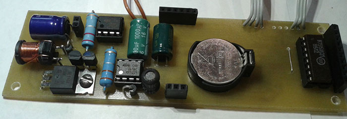
The author pays special attention to the DS1307 clock chip. In the photo, it is in a DIP package, but the wiring for this microcircuit is made as for SMD, so the legs are turned in the other direction, and the microcircuit itself is stuck belly up. Instead of K155ID1, KM155ID1 was used, the author claims that only with the replaced part it was possible to avoid flashes. Placement of elements on the board:


The author has assembled the simplest LPT programmer for programming K ATMega8 (firmware for ATMega8, all boards, firmware for PIC at the end of the article)

PIC programmer:


IN-14 gas discharge indicators have long soft solder leads, but due to their limited resource, it was decided to make them easily replaceable. Therefore, the author used collets from the DIP-microcircuit panel, and shortened the IN-14 legs to the depth of the collets. The holes in the center in the sockets are made specifically for the LEDs, which are located under the lamps on a separate board. The LEDs are connected in parallel, one resistor serves to limit the current per color.

This is what gas-discharge indicators mounted in an aluminum corner look like.
The mount, in the role of which the aluminum corner acts, is etched in ferric chloride, because of this it has aged very visually, which gives more entourage. As it turned out, aluminum reacts very violently with ferric chloride: a very large amount of chlorine and heat is released. Of course, the solution after such tests is no longer suitable for use.

Other details were made using a similar technology (LUT) (the fallout-boy logo, Vault-Tec, as well as the number HB-30YR). The device was intended for a gift to a friend on his 30th birthday. For those who don't understand, the number HB-30YR stands for Happy Birthday - 30 Years :)


The author used a nichrome spiral with antenna F-type connectors at the ends for wiring between the housing and the cover. Fortunately, on the panel right place there were 6 holes, and they served as connectors for wire leads.

Watch before complete assembly. The wires, of course, are not laid out neatly, but this will not affect the functionality in any way.

Power cable. Some old military connectors. The author made the adapter for the plug himself.


Connector for connecting the power cable, as well as a fuse on the surface of the case at the bottom.

View of the device in the closed state. Indeed, it is not much different from the TT-1.


General view of the device.

Stopper to prevent the lid from tipping back.


Watches in the dark look best.


It caused a lot of questions from those who wanted to assemble it, or from those who had already assembled it, and the clock scheme itself underwent some changes, I decided to write another article devoted to watches on gas-discharge indicators. Here I will describe improvements/fixes to both circuitry and firmware.
So, the very first inconvenience when using this watch in an apartment was the brightness. If during the day it did not interfere at all, then at night it illuminated the room well, making it difficult to sleep. This became especially noticeable after the board was redesigned and blue LEDs were installed in the backlight (the red backlight turned out to be an unsuccessful option, because the red light drowned out the glow of the lamps). Reducing the brightness over time did not give a big effect, because. I go to bed at different times, and the clock dims at the same time. Or I am still awake, and the brightness has decreased and the time is not visible. Therefore, I decided to add a light sensor, or, more simply, a photoresistor. Fortunately, there were plenty of ADC outputs for connection. I did not make a direct dependence of brightness on the level of illumination, but simply set five gradations of brightness. The range of ADC values was divided into five intervals, and each interval was given its own brightness value. The measurement is made every second. The new schema node looks like this:
An ordinary photoresistor acts as a light sensor.
The next change affected the power supply scheme of the watch. The fact is that the use of a linear stabilizer imposed restrictions on the supply voltage range, plus the stabilizer itself heated up during operation, especially at full brightness of the LEDs. The heating was weak, but I wanted to get rid of it completely. Therefore, another switching regulator was added to the circuit, this time step-down. The microcircuit remained the same as in the Step-Up converter, only the circuit has changed.

Everything is standard here, from the datasheet. The current required by the circuit for operation is less than 500mA and an external transistor is not needed, the internal key of the microcircuit is enough. As a result, any heating of the supply part of the circuit stopped. In addition, this converter is not afraid of short circuit at the output and overloads. It also takes up less space on the board and protects against accidental polarity reversal of the supply voltage. In general, solid pluses. True, power ripples should have increased, but this has no effect on the operation of the circuit.
In addition to the electronic part, the appearance devices. It no longer has a huge pile of wires. Everything is assembled on two boards, which are folded in a “sandwich” and connected via PLS / PBS connectors. The boards themselves are fastened with screws. On the top board are lamps, anode transistor switches and backlight LEDs. The LEDs themselves are installed behind the lamps, not under them. And on the bottom there are power circuits, as well as MK with strapping (pictured more old version watches that did not yet have a light sensor). Board size 128x38mm.

Lamps IN-17 were replaced by IN-16. They have the same character size, but the form factor is different: After all the lamps became “vertical”, the layout of the board was simplified and the appearance improved.


As you can see in the photo, all the lamps are installed in a kind of sockets. Sockets for IN-8 are made of D-SUB connector pins in female format. After removing the metal frame, he easily and naturally parted with these same contacts. The connector itself looks like this:

And for IN-16 from the contacts of a conventional collet ruler:

I think that we should immediately put an end to possible questions about the need for such a decision. Firstly, there is always a risk of breaking the lamp (maybe the cat will climb in or the wire will be pulled, in general, anything can happen). And secondly, the thickness of the connector pin is much less than the thickness of the lamp pin, which greatly simplifies the layout of the board. Plus, when soldering the lamp into the board, there is a danger of a violation of the tightness of the lamp due to overheating of the output.
Well, as usual, the scheme of the entire device:

And video of work:
They work stably, no bugs have been identified for six months of work. In the summer we stood for more than a month without food while I was away. I arrived, turned it on - time did not run away anywhere and the operating mode did not go astray.
The clock is controlled as follows. By briefly pressing the BUTTON1 button, the operating mode is switched (CLOCK, CLOCK + DATE, CLOCK + TEMPERATURE, CLOCK + DATE + TEMPERATURE). When you hold the same button, the time and date setting mode is turned on. Changing the readings is carried out with the BUTTON2 and BUTTON3 buttons, and the transition through the settings is carried out by briefly pressing BUTTON1. Turning the backlight on/off is done by holding the BUTTON3 button.
Now you can go to next version scheme. It was made on only four IN-14 lamps. There is simply no place to get small lamps for seconds, as, in other matters, and IN-8. But buy IN-14 at reasonable price poses no problems.
There are almost no differences in the circuit, the same two switching power converters, the same AtMega8 microcontroller, the same anode switches. The same RGB backlight... Stop, there was no RGB backlight. So there are differences! Now the clock can glow in different colors. Moreover, the program provides the ability to sort through the enumeration of colors in a circle, as well as the possibility of fixing the color you like. Naturally, with the preservation of the color itself and the mode of operation in the non-volatile memory of the MK. I thought for a long time how it would be more interesting to use the points (there are two of them in each lamp) and in the end I brought seconds to them in binary format. Tens of seconds go on the lamps of hours, and units on the lamps of minutes. Accordingly, if we have, for example, 32 seconds, then the number 3 will be made from the points of the left lamps, and the number 2 from the right lamps.
The form factor remained “sandwich”. On the bottom board there are two converters for powering the circuit, MK, K155ID1, DS1307 with a battery, a photoresistor, a temperature sensor (now there is only one) and transistor switches for lamp points, and RGB backlights.
And on the top there are anode keys (by the way, they are now in SMD version), lamps and backlight LEDs.


All in all it looks pretty good.


Well, the video of the work:
The clock is controlled as follows. By briefly pressing the BUTTON button1 switches the operating mode (CLOCK, CLOCK+DATE,CLOCK+TEMPERATURE,CLOCK+DATE+TEMPERATURE). When you hold the same button, the time and date setting mode is turned on. Changing the readings is carried out with the BUTTON2 and BUTTON3 buttons, and the transition through the settings is carried out by briefly pressing BUTTON1. Changing the illumination backlight modes is carried out by briefly pressing the BUTTON3 button.
The fuses remained the same as in the first article. The MK is powered by an internal 8 MHz oscillator.In hexadecimal:HIGH: D9, LOW: D4 and picture:

MK firmware, sources and printed circuit boards format are attached.
List of radio elements
| Designation | Type of | Denomination | Quantity | Note | Score | My notepad | |
|---|---|---|---|---|---|---|---|
| With RGB backlight | |||||||
| U1 | Chip | K155ID1 | 1 | To notepad | |||
| U2 | MK AVR 8-bit | ATmega8A-AU | 1 | To notepad | |||
| U3 | Real time clock (RTC) | DS1307 | 1 | To notepad | |||
| U4, U5 | DC/DC switching converter | MC34063A | 2 | To notepad | |||
| P9 | temperature sensor | DS18B20 | 1 | To notepad | |||
| Q1, Q2, Q7-Q10 | bipolar transistor | MPSA42 | 6 | MMBTA42 | To notepad | ||
| Q2, Q4-Q6 | bipolar transistor | MPSA92 | 4 | MMBTA92 | To notepad | ||
| Q11-Q13, Q16 | bipolar transistor | BC857 | 4 | To notepad | |||
| Q14 | bipolar transistor | BC847 | 1 | To notepad | |||
| Q15 | MOSFET transistor | IRF840 | 1 | To notepad | |||
| D1 | rectifier diode | HER106 | 1 | To notepad | |||
| D2 | Schottky diode | 1N5819 | 1 | To notepad | |||
| L1, L2 | Inductor | 220uH | 2 | To notepad | |||
| Z1 | Quartz | 32.768 kHz | 1 | To notepad | |||
| BT1 | Battery | Battery 3V | 1 | To notepad | |||
| HL1-HL4 | Light-emitting diode | RGB | 4 | To notepad | |||
| R1-R4 | Resistor | 12 kOhm | 4 | To notepad | |||
| R5, R7, R9, R11, R34, R35 | Resistor | 10 kOhm | 6 | To notepad | |||
| R8, R10, R12, R14 | Resistor | 1 MΩ | 4 | To notepad | |||
| R13-R18, R37, R38, R40 | Resistor | 1 kOhm | 9 | To notepad | |||
| R19, R20, R33, R39, R41-R43, R46, R47, R51, R53 | Resistor | 4.7 kOhm | 11 | To notepad | |||
| R21, R24, R27, R30 | Resistor | 68 ohm | 4 | To notepad | |||
| R22, R23, R25, R26, R28, R29, R31, R32 | Resistor | 100 ohm | 8 | To notepad | |||
| R36 | Resistor | 20 kOhm | 1 | To notepad | |||
| R44 | Resistor | ||||||
Hello users again and keep the promise!
Today I'm starting to post a detailed photo report on the manufacture of watches on gas discharge indicators (GDI). Based on IN-14.
All manipulations in this and the following posts are available to a person without experience, you just need to have a little skill. I will divide the work into several parts, each of which will be described in detail by me and posted on the network.
We proceed to the first stage - etching the boards. After researching the literature, I found several technologies:
- . It needs three components to work: laser printer, ferric chloride and iron. The method is the easiest and cheapest. He has only one minus - it is difficult to transfer very thin tracks.
- Photo resist. The following materials are needed for work: photo-razist, printer film, soda ash and a UV lamp. The method allows etching boards at home. The downside is that it's not cheap.
- Reactive ion etching (RIE). Reactive plasma is needed for work, therefore it is not feasible at home.
Anode etching is most commonly used. The process of anodic etching consists in the electrolytic dissolution of the metal and the mechanical separation of oxides by the released oxygen.
It is quite understandable that I chose the LUT method for etching boards. Scroll necessary equipment and materials should look something like this:
- Ferric chloride. He is bathed in radio products at a price of 100-150 rubles per can.
- Foil fiberglass. Can be found in radio stores, radio flea markets or factories.
- Capacity. A regular food container will do.
- Iron.
- Glossy paper. Self-adhesive paper or a plain page of a glossy magazine will do.
- Laser printer.
IMPORTANT! The print version must be a mirror image, because when the image is transferred from paper to copper, it will be displayed back.
It is necessary to mark up and cut off a piece of textolite for the board. This is done with a hacksaw, a breadboard knife, or, as in my case, a drill.
After that, I cut out a sketch of the future board from paper and attached the pattern to the textolite (from the foil side). Paper is taken with a margin in order to wrap the textolite. We fix the sheet on the back side with adhesive tape for fixing.
From the side of the drawing, we draw along the future board with an iron several times through sheet A4. It will take at least 2 minutes of intensive “ironing” to transfer the toner to copper.
We substitute the workpiece under a stream of cold water and easily remove the paper layer (wet paper should come off freely by itself). If the heating of the surface was insufficient, small pieces of toner may come off. We finish them with cheap nail polish. As a result, the blank for the board should look like this:
In the prepared container, we prepare a solution of ferric chloride and water. It is better to use hot water for these purposes, this will increase the reaction rate. It is better to refuse boiling water, because heat deforms the board. The finished liquid should have the color of medium tea leaves. We place the board in the solution and wait until the excess foil is completely dissolved.
If you occasionally stir the solution in the container, the reaction rate will also increase. For the skin of the hands, ferric chloride is not dangerous, but the fingers can be stained.
To give greater clarity to the process, I placed the board in the solution partially. What changes should take place can be seen in the photo:
Excess copper dissolves in the composition after about 40 minutes. After that, the etching process can be considered completed. It remains only to make a few holes. We mark with an awl and drill small holes with a drill. The tool must run at high speed so that the drill does not move out. The result of the work should look something like this:
The second stage in the manufacture of watches on the GRI is the soldering of the components. I will talk about this in my next post.
Downloading:
- Program ).
- Post about soldering components -;
- Post about microcontroller firmware -;
- A post about making a case -.
Handy fringe cutter for transformers. Soldering iron heating regulator with power indicator
Hello dear readers. For a long time I wanted to assemble a watch on gas discharge indicators, but there was sorely lack of time, finally I finished this project. Under the cut, a little about what gas-discharge indicators are, as well as how I assembled the watch, starting with the circuit and ending with the case.
Introduction
According to Wikipedia, the first gas discharge indicators were developed in the 50s of the last century. Abroad, such indicators are called "Nixie", the name comes from the abbreviation "NIX 1" - "Numerical Indicator eXperimental 1" (" digital indicator experimental, development 1"). This watch uses iconic Soviet-made indicators of the IN-12B type.
By design, they are a glass flask inside which there are ten thin metal electrodes (cathodes), each of which corresponds to one digit from 0 to 9, the electrodes are stacked so that different numbers appear at different depths. There is also one electrode in the form of a metal mesh (anode), located in front of all the others. The flask is filled with an inert gas, neon, with a small amount of mercury. When an electrical potential of 120 to 180 volts is applied between the anode and cathode direct current, a glow appears near the cathode, the corresponding figure lights up. This soft orange light is what these indicators are valued for.
Additional Information
To be precise, there is another cathode in the IN-12B lamps - in the form of a point, it is not used in this watch.
Also in this watch, another gas-discharge indicator, INS-1, is used to separate hours and minutes.  The indication is carried out through the lens dome of the cylinder, it looks like a luminous dot of orange color.
Scheme
The clock scheme was found on the Internet, by Timofey Nosov. It is based on the PIC16F628A microcontroller and the Soviet K155ID1 microcircuit, which is a high-voltage decoder for controlling gas-discharge indicators.
The lamps are powered by a step-up switching converter assembled on field effect transistor, inductance, capacitor and diode, the PWM signal is generated by the microcontroller. This scheme uses dynamic indication, the microcontroller, using the K155ID1 decoder, controls the cathodes of all lamps at once, synchronously controls the anodes of the lamps through optocouplers. The switching speed of the lamps occurs at a high frequency, and since gas-discharge indicators, like any lamp, need time to go out, the human eye does not see the flicker (I will say more - even the camera does not see).
The circuit implements backup power on the CR2032 element, when the power is turned off, the indication goes out, and the clock continues to run.
Electronic part
The clock circuit is divided into two parts - a board with lamps and the main board of the device. Link to the archive with the file for Splint Layout -
 With the help of LUT I made two boards 
We collect a board with lamps 
 I got the lamps from the old Soviet technology, in fact, this find prompted me to collect this watch.
We collect the main fee 

The boards are connected via PLS and PBS connectors, which are soldered from the side of the tracks. This is what it looks like assembled: 
 Microcontroller PIC16F628A bought -
Optocouplers bought -
FET IFR840 -
The rest was available, or found in place.
It remains to flash the microcontroller. We will flash using the PICkit2 programmer, I bought it a long time ago - 
We launch the PICkit2 program and flash our microcontroller  After the firmware, I turn on the clock ... but the numbers do not light up, only the second indicator (INS-1) blinks. After I found my mistake, instead of a 4.7K resistor, 47K was installed in the lamp power circuit. After the replacement, the circuit worked, it is necessary to make a case.
Frame
I still have a piece of beech timber, this is the same beech that was used to make the “shaitan box” case from mine.
At first I wanted to cut the case on a CNC machine, I agreed with my friend working in the furniture industry. But, as it happens, there is no time, then another work urgently needs to be done. In short, after a month of waiting, I decided to do it myself.
I cut out a blank for the future building, marked 
I cut out a cavity for the insides, it was the laborious stage itself. First, I drilled, then removed the excess with a chisel, then sanded it. 
With a chisel I made a recess for the glass and the back panel, glued the stops inside the case, soaked everything with linseed oil 

I cut a piece of the desired size from tinted glass 
I made a back panel with holes for buttons and a power connector 
Put it all together, front view 
Back view 
In order for the watch to stand a little at an angle, I glued two rubber feet on the bottom 
In the case of a rare inclusion of individual indicator cathodes and the activity of others, metal particles sputtered by operating cathodes settle on rarely used ones, which contributes to their "poisoning". The device implements a method of dealing with this phenomenon, before changing the minutes, a quick enumeration of all the digits in all the lamps takes place. Demonstration how it works: 
From the functional - clock, alarm clock, brightness adjustment. Management is carried out by three buttons - "more", "ok" and "less".
By pressing the OK button, the following modes are selected:
– setting the clock of the current time (HH _ _);
– setting the minutes of the current time (_ _ MM);
– setting the alarm clock (HH._ _);
– setting the alarm minutes (_ _.MM);
– setting of the current day of the week from 1 to 7 (0 _ _ 1);
– wake-up call on Monday (1 _ _ 1);
– alarm on Tuesday (2 _ _ 1);
– wake-up call on Wednesday (3 _ _ 1);
– alarm on Thursday (4 _ _ 1);
– alarm on Friday (5 _ _ 1);
– alarm on Saturday (6 _ _ 0);
– wake-up call on Sunday (7 _ _ 0);
- the brightness of the glow of the lamps from 0 to 20 (8 _ 05);
– hourly signal from 9:00 to 21:00 (9 _ _ 1).
This is how this beauty looks in the dark 


As a result, we have a beautiful thing made with our own hands. In the future, I will probably make other watches in a different case, there is one idea.
Thank you all for your attention. Add to favorites Liked +209 +319