It is noteworthy that analog walkie-talkies have been used for civil communications since 1933, and for military purposes they began to be used twenty years earlier. Since then, of course, they have undergone all sorts of improvements and improvements. Now analog walkie-talkies are the limit of perfection. However, the advent of digital walkie-talkies has made a grand revolution in radio technology.
If we compare analog and digital devices, they differ significantly not only in the method of signaling, but also in sound quality and price ratio. But, despite the clear advantages of digital devices, they can never completely replace analog walkie-talkies. They are still used in various areas of life.
Digital and analog signal: comparative characteristics
Basically, analog walkie-talkies use frequency modulation, that is, FM waves. This is a type of modulation in which the sound signal controls the frequency of the carrier wave. The cost of an analog walkie-talkie is low due to the fact that it was possible to integrate this system with just one chip. An analog signal is used in many modern walkie-talkies, but the advent of digital systems has reduced their popularity.Digital signal - represented by binary numbers 0 and 1. Digital transmission methods guarantee the transmission of all necessary data due to error correction and control bits. Algorithms software perfectly distinguish background noise from the useful signal.
Digital wireless transmission data guarantees the same reliable information delivery as a wired system.
Walkie-talkie - a popular means of communication?
There is an opinion that walkie-talkies are a dying technology. Actually, it is wrong. Walkie-talkies are still in demand and popular means of communication as they allow:- Instant messaging
- Talk to multiple people at the same time
- Durable in operation, and work in any conditions
Digital and analog devices have almost the same functions, but their differences are significant.
Analog walkie-talkies: advantages and disadvantages
The advantages of analog walkie-talkies can be safely considered:- The sound is transmitted unencrypted, which is very popular with most users.
- A huge range of different models and a choice of all kinds of accessories
- Ease of operation and user understanding of frequency usage
- You can only have one conversation per channel at a time.
- The need for a transmitter and receiver specifically tuned to the same frequency
- Inability to use programs designed for business
Digital walkie-talkies: advantages and disadvantages
The benefits of digital radios include:- Excellent noise suppression
- Excellent sound quality at any distance
- Possibility to have multiple conversations on one channel at the same time
- Ability to send short messages
- High channel density
- Signals are received by standard antennas
- Digital processing reduces background noise
- Availability of software
- The digital platform allows you to use both analog and digital walkie-talkies at the same time
- You can track the movement of interlocutors in the same network
- High price
- Long-term training in use
- RF noise interferes with digital signal, error may occur
From all of the above, we can conclude that digital radio stations differ from analog ones in the presence of higher operational and functional characteristics. The main advantage of digital devices is the higher stability of the signal in the presence of interference. That is why they become popular.
The difference between analog and digital communications.
When dealing with radio communications, one often encounters terms such as "analog signal" and "digital signal". For specialists, there is no mystery in these words, but for ignorant people, the difference between “digital” and “analogue” may be completely unknown. And yet there is a very significant difference.
So. Radio communication is always the transmission of information (voice, SMS, telesignaling) between two subscribers, a signal source transmitter (radio station, repeater, base station) and a receiver.
When we talk about a signal, we usually mean electromagnetic oscillations, inducing EMF and causing current fluctuations in the receiver antenna. Further, the receiving device translates the received vibrations back into an audio frequency signal and outputs it to the speaker.
In any case, the transmitter signal can be represented in both digital and analog form. After all, for example, the sound itself is an analog signal. At the radio station, the sound perceived by the microphone is converted into the already mentioned electromagnetic oscillations. The higher the frequency of the sound, the higher the oscillation frequency at the output, and the louder the speaker speaks, the greater the amplitude.  The resulting electromagnetic oscillations, or waves, propagate in space with the help of a transmitting antenna. So that the air is not clogged with low-frequency interference, and so that different radio stations have the opportunity to work in parallel without interfering with each other, the vibrations resulting from the impact of sound are summed up, that is, they are “superimposed” on other vibrations that have a constant frequency. The last frequency is usually called the "carrier", and it is on its perception that we tune our radio receiver in order to "catch" the analog signal of the radio station.
The reverse process occurs in the receiver: the carrier frequency is separated, and the electromagnetic oscillations received by the antenna are converted into sound oscillations, and the information that the sender wanted to convey is heard from the speaker.
In the process of transfer sound signal third-party interference may occur from the radio station to the receiver, the frequency and amplitude may change, which, of course, will be reflected in the sounds emitted by the radio receiver. Finally, both the transmitter and receiver themselves introduce some error during signal conversion. Therefore, the sound reproduced by an analog radio always has some distortion. The voice may be perfectly reproduced, despite the changes, but there will be hissing or even some kind of wheezing caused by interference in the background. The less confident the reception, the louder and more distinct these extraneous noise effects will be.  In addition, the terrestrial analog signal has a very weak degree of protection against unauthorized access. For public radio stations, this, of course, does not matter. But during the use of the first mobile phones, there was one unpleasant moment associated with the fact that almost any extraneous radio receiver could easily be tuned to the right wave to eavesdrop on your telephone conversation.
To protect against this, the so-called “toning” of the signal or, in another way, the CTCSS (Continuous Tone-Coded Squelch System) system is used, a noise reduction system encoded by a continuous tone or a “friend / foe” signal identification system designed to separate users working in the same frequency range, into groups. Users (correspondents) from the same group can hear each other thanks to identification code. Explaining clearly, the principle of operation of this system is as follows. Along with the transmitted information, an additional signal (or another tone) is also sent on the air. The receiver, in addition to the carrier, recognizes this tone with the appropriate setting and receives the signal. If the tone is not set in the radio-receiver, then the signal is not received. There are quite a few encryption standards that vary from manufacturer to manufacturer.
Analog broadcasting has such shortcomings. Because of them, for example, television promises to become completely digital in a relatively short time.  Digital communication and broadcasting are considered to be more protected from interference and from external influences. The thing is that when using the "numbers" the analog signal from the microphone at the transmitting station is encrypted into a digital code. No, of course, the flow of figures and numbers does not spread into the surrounding space. It's just that the sound of a certain frequency and volume is assigned a code from radio pulses. The duration and frequency of the pulses are set in advance - it is the same for both the transmitter and the receiver. The presence of a pulse corresponds to one, the absence corresponds to zero. Therefore, such a connection is called "digital".
A device that converts an analog signal into a digital code is called analog-to-digital converter (ADC). And a device installed in the receiver that converts the code into an analog signal corresponding to the voice of your friend in the speaker cell phone GSM standard, called a digital-to-analog converter (DAC).
During the transmission of a digital signal, errors and distortions are practically excluded. If the impulse becomes a little stronger, longer, or vice versa, then it will still be recognized by the system as a unit. And zero will remain zero, even if some random weak signal. For ADC and DAC, there are no other values than 0.2 or 0.9 - only zero and one. Therefore, interference on digital communications and broadcasting has almost no effect.
Moreover, the “digit” is also more protected from unauthorized access. Indeed, in order for the DAC of the device to be able to decrypt the signal, it is necessary that it “know” the decryption code. The ADC, along with the signal, can also transmit the digital address of the device selected as the receiver. Thus, even if the radio signal is intercepted, it cannot be recognized due to the absence of at least part of the code. This is especially true for communication.
So, differences between digital and analog signals:
1) An analog signal can be distorted by interference, and a digital signal can either be completely jammed with interference, or come without distortion. A digital signal is either exactly there, or completely absent (either zero or one).
2) The analog signal is available for perception by all devices operating on the same principle as the transmitter. The digital signal is securely coded and hard to intercept if it's not intended for you.  In addition to purely analog and purely digital stations, there are radio stations that support both analog and digital modes. They are designed to transition from analog to digital communications.
So, having at your disposal a fleet of analog radio stations, you can gradually switch to a digital communication standard.
For example, you initially built a communication system at Baikal 30 Radio Stations.
Let me remind you that this is an analog station with 16 channels.  But time goes by, and the station ceases to suit you as a user. Yes, it is reliable, yes powerful, yes with good battery up to 2600 mAh. But with the expansion of the park of radio stations by more than 100 people, and especially when working in groups, its 16 channels begin to be missed.
You don't have to run out and buy digital standard radios right away. Most manufacturers deliberately introduce a model with an analog transmission mode.
That is, you can gradually switch to, for example, Baikal-501 or Vertex-EVX531 while keeping the existing communication system in working condition.
The advantages of such a transition are undeniable.
You get a working station
1) longer (in digital mode, less consumption.)
2) Having more functions (group call, lone worker)
3) 32 memory channels.
That is, you actually create initially 2 channel bases. For new purchased stations ( digital channels) and a base of assistance channels with existing stations (analogue channels). Gradually, as you purchase equipment, you will reduce the fleet of radio stations of the second bank and increase the first one.
In the end, you will achieve your goal - to completely transfer your base to a digital communication standard.
The Yaesu Fusion DR-1 digital repeater can serve as a good addition and extension to any base. 
This is a dual-band (144/430MHz) repeater that supports analog FM communication as well as digital protocol simultaneously. System Fusion
within the frequency range of 12.5 kHz. We are confident that the introduction of the latest DR-1X will be the dawn of our new and impressive multifunctional system system fusion.
One of the key opportunities System Fusion
is a function AMS (automatic mode selection) which instantly recognizes whether a signal is being received in V/D mode, voice communication or data mode FR analog FM or digital C4FM, and automatically switches to the corresponding one. Thus, thanks to our digital transceivers FT1DR and FTM-400DRSystem Fusion
to keep in touch with analogue FM radio stations, there is no longer a need to manually switch modes each time.
On repeater DR-1X, AMS can be configured so that an incoming digital C4FM signal is converted to analogue FM and rebroadcast, thus allowing communication between digital and analogue transceivers. AMS can also be configured to automatically relay the input mode to the output, allowing digital and analog users to share the same repeater.
Until now, FM repeaters have only been used for traditional FM communications, and digital repeaters for digital only. However, now by simply replacing the conventional analog FM repeater with DR-1X, you can continue to use normal FM communication and also use the repeater for more advanced digital radio communication System Fusion
. Other peripherals such as duplexer and amplifier, etc. can continue to be used as usual.
More detailed characteristics of the equipment can be seen on the website in the products section.
Signals are information codes that are used by people in order to transmit messages in an information system. The signal may be given, but it is not necessary to receive it. Whereas a message can be considered only such a signal (or a set of signals) that was received and decoded by the recipient (analogue and digital signal).
One of the first methods of transmitting information without the participation of people or other living beings were signal fires. When danger arose, bonfires were successively lit from one post to another. Next, we will consider the method of transmitting information using electromagnetic signals and dwell on the topic in detail. analog and digital signal.
Any signal can be represented as a function that describes changes in its characteristics. This representation is convenient for studying devices and systems of radio engineering. In addition to the signal in radio engineering, there is also noise, which is its alternative. Noise carries no useful information and distorts the signal by interacting with it.
The concept itself makes it possible to abstract from specific physical quantities when considering phenomena associated with encoding and decoding information. The mathematical model of the signal in research allows relying on the parameters of the time function.
Signal types
Signals according to the physical medium of the information carrier are divided into electrical, optical, acoustic and electromagnetic.
According to the method of setting the signal can be regular and irregular. A regular signal is represented by a deterministic function of time. An irregular signal in radio engineering is represented by a chaotic function of time and is analyzed using a probabilistic approach.
Signals, depending on the function that describes their parameters, can be analog and discrete. A discrete signal that has been quantized is called a digital signal.
Signal processing
The analog and digital signal is processed and directed to transmit and receive the information encoded in the signal. Once the information has been extracted, it can be used in different purposes. In particular cases, information is formatted.
Analog signals are amplified, filtered, modulated and demodulated. Digital, in addition to this, can still be compressed, detected, etc.
analog signal
Our sense organs perceive all the information coming into them in an analog form. For example, if we see a car passing by, we see its movement continuously. If our brain could receive information about its position once every 10 seconds, people would constantly get under the wheels. But we can estimate the distance much faster and this distance at any given time is clearly defined.

Absolutely the same thing happens with other information, we can evaluate the volume at any time, feel how much pressure our fingers put on objects, etc. In other words, almost all information that can arise in nature has an analog form. The easiest way to transmit such information is with analog signals, which are continuous and defined at any given time.
To understand what an analog electrical signal looks like, you can imagine a graph showing amplitude on the vertical axis and time on the horizontal axis. If we, for example, measure the change in temperature, then a continuous line will appear on the graph, displaying its value at each point in time. To send such a signal with electric current, we need to compare the temperature value with the voltage value. So, for example, 35.342 degrees Celsius can be encoded as a voltage of 3.5342 V.
Analog signals used to be used in all types of communications. To avoid interference, such a signal must be amplified. The higher the level of noise, that is, interference, the stronger the signal must be amplified so that it can be received without distortion. This method of signal processing consumes a lot of energy to generate heat. Wherein amplified signal may itself cause interference to other communication channels.
Now analog signals are still used in television and radio, to convert the input signal in microphones. But, in general, this type of signal is universally superseded or superseded by digital signals.
digital signal
The digital signal is represented by the sequence digital values. The most commonly used now are binary digital signals, as they are used in binary electronics and are easier to encode.

Unlike the previous signal type, the digital signal has two values "1" and "0". If we recall our example with temperature measurement, then here the signal will be formed differently. If the voltage supplied by the analog signal corresponds to the value of the measured temperature, then a certain number of voltage pulses will be applied in the digital signal for each temperature value. The voltage pulse itself here will be equal to "1", and the absence of voltage - "0". The receiving equipment will decode the pulses and restore the original data.
Having imagined how the digital signal will look on the chart, we will see that the transition from zero value to the maximum is made sharply. It is this feature that allows the receiving equipment to “see” the signal more clearly. If any interference occurs, it is easier for the receiver to decode the signal than with analog transmission.

However, it is impossible to restore a digital signal with a very high noise level, while it is still possible to “fish out” information from an analog type with high distortion. This is due to the clipping effect. The essence of the effect is that digital signals can be transmitted over certain distances, and then simply cut off. This effect occurs everywhere and is solved by a simple signal regeneration. Where the signal breaks, you need to insert a repeater or reduce the length of the communication line. The repeater does not amplify the signal, but recognizes its original form and produces an exact copy of it and can be used arbitrarily in the circuit. Such methods of signal repetition are actively used in network technologies.
Among other things, analog and digital signals differ in the ability to encode and encrypt information. This is one of the reasons for the transition mobile communications to "number".
Analog and digital signal and digital-to-analog conversion
It is necessary to talk a little more about how analog information is transmitted over digital communication channels. Let's go back to the examples. As already mentioned, sound is an analog signal.
What's going on in mobile phones that transmit information over digital channels
The sound entering the microphone is subjected to analog-to-digital conversion (ADC). This process consists of 3 steps. Separate signal values are taken at regular intervals, this process is called sampling. According to the Kotelnikov theorem on bandwidth channels, the frequency of taking these values should be twice as high as the highest frequency of the signal. That is, if our channel has a frequency limit of 4 kHz, then the sampling frequency will be 8 kHz. Further, all selected signal values are rounded or, in other words, quantized. The more levels this creates, the higher the accuracy of the reconstructed signal at the receiver. Then all values are converted to binary code, which is transmitted to base station and then reaches the other subscriber, which is the receiver. A digital-to-analog conversion (DAC) process takes place in the receiver's phone. This is an inverse procedure, the purpose of which is to get the output as close as possible to the original signal. Further, the analog signal comes out in the form of sound from the phone's speaker.
Analogue communication channels
Analog communication channels are the most common due to their long history of development and ease of implementation. A typical example of an analog channel is a tone frequency channel (telephony).
The need for modulation of analog information arises when it is necessary to transmit a low-frequency analog signal through a channel located in the high-frequency region of the spectrum.
Examples of such a situation are the transmission of voice over radio and television. Voice has a spectrum about 10 kHz wide, while radio bands include much higher frequencies, from 30 kHz to 300 MHz. Even higher frequencies are used in television. Obviously, the voice cannot be transmitted directly through such a medium.
modulation called signal transformation, which consists in changing any of its information parameters in accordance with the transmitted message.

The transmitted information is embedded in the control (modulating) signal, and the role of the information carrier is performed by a high-frequency oscillation called the carrier. Modulation, therefore, is the process of "landing" an information wave on a known carrier.
Analog modulation is a physical coding method in which information is encoded by changing the amplitude, frequency, or phase of a sinusoidal carrier signal.

Amplitude modulation (AM)- modulation in which the amplitude of the carrier wave is controlled by an information (modulating) signal.
Frequency modulation (FM)- modulation in which the frequency of the carrier wave is controlled by an information (modulating) signal.
Phase Modulation (PM)- modulation in which the phase of the carrier wave is controlled by an information (modulating) signal.
Digital communication channels
Digital communication channels include ISDN, T1/E1 channels.
When transmitting discrete data over communication channels, two main types of physical coding are used - based on a sinusoidal carrier signal and based on a sequence rectangular pulses. The first method is often called analog modulation or keying, emphasizing the fact that coding is carried out by changing the parameters of the analog signal. The second method is usually called digital coding. These methods differ in the width of the spectrum of the resulting signal and the complexity of the equipment required for their implementation.
Analog Discrete Data Modulation
The need to apply analog modulation to the transmission of discrete data arises when it is necessary to transmit computer data over telephone channels.
A device that performs the functions of modulating a carrier sinusoid on the transmitting side and demodulating on the receiving side is called a modem (modulator - demodulator).
The main methods of analog modulation of discrete data:

With amplitude modulation AM, for a logical one, one level of the amplitude of the carrier frequency sinusoid is selected, and for a logical zero, another. This method is rarely used in its pure form in practice due to low noise immunity, but is often used in combination with another type of modulation - phase modulation.
With FM frequency modulation, the values 0 and 1 of the original data are transmitted as sinusoids with different frequencies. This modulation method does not require complex circuits in modems and is usually used in low-speed modems operating at 300 or 1200 bps.
In PM phase modulation, data values 0 and 1 correspond to signals of the same frequency but different phase, such as 0 and 180 degrees or 0.90,180 and 270 degrees.
In high-speed modems, combined modulation methods are often used, as a rule, amplitude, in combination with phase.
Digital coding of communication channels
When digitally encoding discrete information, potential and impulse codes are used.
In potential codes, only the value of the signal potential is used to represent logical ones and zeros, and its drops, which form complete pulses, are not taken into account. Pulse codes allow binary data to be represented either by pulses of a certain polarity, or by a part of the pulse - by a potential drop of a certain direction.
Requirements for digital coding methods:
- had at the same bit rate the smallest width of the spectrum of the resulting signal;
- provided synchronization between transmitter and receiver;
- had the ability to recognize mistakes;
- had a low cost of implementation.
A narrower range of digital signals allows for the same line (with the same bandwidth) to achieve more high speed data transmission. In addition, the requirement is often imposed on the signal spectrum that there is no constant component, that is, the presence of direct current between transmitter and receiver. In particular, the use of various transformer circuits galvanic isolation prevents the flow of direct current.
Synchronization of the transmitter and receiver is needed so that the receiver knows exactly at what point in time it is necessary to read new information from the communication line. This problem is more difficult to solve in networks than in the exchange of data between closely spaced devices. On the short distances a scheme based on a separate clocking communication line works well.

In networks, the use of this scheme causes difficulties due to:
- Heterogeneity of characteristics of conductors in cables. Over long distances, signal velocity ripples can cause the clock to arrive so late or too early for the corresponding data signal that a data bit is skipped or reread.
- Saving conductors in expensive cables.
Therefore, so-called self-synchronizing codes are used in networks. Any sharp edge in the signal - the so-called front - can be a good indication for synchronization of the receiver with the transmitter.
Historically, Schilling's telegraph (1832) is considered the first attempt to transmit a figure. Gradually, the inventor, trying to reduce the number of connecting lines, introduced a technique for encoding printed characters in two states. Morse code (1840) works similarly.
Digital communication is a type of telecommunication that uses discrete signals, usually binary system reckoning.
History of information coding in terms of communication
We consider it superfluous to mention the smoke of the fire of cavemen, which is disgusting to readers. Chappe's semaphore is an equally useless example. And then Wikipedia reported: Leibniz, the founder of binary counting, was interested in the Chinese Book of Changes ... Today, the deepest ancient knowledge is underestimated by the ignoramuses who squeamishly discard the misunderstood. Let's take the narrow path.
The ancient inhabitants of Malaysia used a combined binary-decimal number system. The ritual drums of Africa formed a code signal that served various purposes.
Ancient Egypt
Wikipedia will not let you lie - the Egyptians knew how to count well. There were even two types of fractions:
- The Egyptians got their own name. There was a record of a number as a finite sum of simple fractions. Mathematicians have proven that every positive rational number is decomposed in the specified way. The technique was adopted by many ancient civilizations.
- Eye of Horus (reminiscent of the Eye of Ra), the sign gives protection, royalty, excellent health. Modern researchers gave the image their own names, noting the similarity of individual elements with numbers.
Eyes of Horus
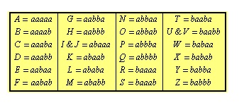
Horus is considered the son of Osiris and Isis. Traditionally endowed with the head of a falcon. The right eye of ancient images personifies the sun god Ra, the left eye - the god of wisdom Thoth. Both are mirror reflections each other. The hieroglyphs denoting the eye make sense: doer; person doing work. The various sections of the image represented one divided by the first 6 powers of two, reminiscent of a modern binary code:
- 1/2. Right side of the eye.
- 1/4. Eyeball.
- 1/8. Eyebrow.
- 1/16. Left-hand side.
- 1/32. Bend, curl, imitating a wrinkle below the eye.
- 1/64. A trail of tears.
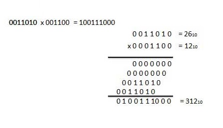
In 2003, Jim Ritter finally proved the inconsistency of the theory of the similarity of eye elements with hieroglyphs denoting numbers. However, the terminology has taken root and continues to be actively used by mathematicians. The Egyptians used divisors by the degree of twos, counting the harvest, the volume of liquids. The first traces of use date back to 2400 BC. The multiplication procedure uses an algorithm that includes the binary representation of the second number.

Book of Changes
A document dated to the ninth century. BC, demonstrates a system of divination in the quaternary number system. The base system is formed by:
- The dual nature of forces: yin, yang.
- Eight trigrams of Boudois (total: third power of two).
- 64 Lushisygua hexagrams (total: sixth power of two).
Shao Yong arranged the hexagrams according to ascending order, creating a set of numbers. Never tried to use pictures while doing math though.
India
The ancient scholar Pingala (2nd century BC) developed a rhythmic system of versification, reminiscent of Morse code - long / short syllables. The treatise Chandas-shastra became a ritual classic accompanying the Vedas. The information is described by a matrix that helps to provide the poem with a unique rhythm. There is no modern binary analogue.
Medieval binary system
In 1605, Francis Bacon considered the system binary encoding letters, offering visual system recognition of encrypted information. Along the way, he mentioned the possibility of using:
- Bells.
- Lights.
- Torches.
- Musket salvos.
- Trumpet melodies.
John Napier (1617) described a system of binary calculations. Thomas Harriot was interested in the question, too lazy to publish the results. Later, the papers were found among the manuscripts of the scientist. The work of Juan Caramuel and Lobkowitz (1670) is considered the first thematic manuscript. The section Ru binara arithmetica introduces the concept of a binary system:
- 1 = a.
- 0 = about.
Along the way, the theologian mentions the possibility of using bases above decimal, suggesting replacing the missing numbers with letters. 32 = aoooh. It is still used by modern computing systems. The scientist tried to show: binary reckoning was suggested by nature. Lobkowitz relied on the musical structure of the instruments. Weaving intricate ideas of philosophy, he pointed out the heavenly background of the application of the ternary system. Four directions of the world linked to the fourfold.
Similar paths moved the thoughts of Harriot, whose work was a mystery to his contemporaries.
Leibniz
Leibniz became interested in the problem in 1979. The first acquaintance with the Chinese rarity is due to a member of the missionary community, Joachim Bouvet, who personally visited (1685) the country of silk. The hexagrams confirmed the universality of Leibniz's own Christian worldviews. Let us illustrate the not obvious train of thought of the scientist:
- Christ was created from nothing (Ex nihilo) by the command of God. Contrasted with other people created from matter. “It is not easy to convey to the Gentiles the concept of creation from nothing through the power of God. Now everyone can think of a wonderful number system, where the world is represented by the number 1, nothing by the number 0.” Quotation from a letter to the Duke of Brunswick, with hexagrams attached.
- The link Being/Nothing forms a dualistic system.
- Binary counting is a gift from heaven.
Twenty-five years later, an essay Explanation of Binary Arithmetic Using the Numbers 0 and 1 was published, supplemented by an explanation of the usefulness and connection with the Chinese Fu Xi figures. The semantic representation of values is identical to the generally accepted modern one. The scientist took the trouble to build hexagrams (see above), having received a powerful means of making calculations.
Binary arithmetic
George Boole (1854) created the famous logic, which received a unique name by the will of the community of mathematicians. Logic has become the basis for the design of modern digital devices. Claude Shannon (1937, Massachusetts Institute of Technology) formulated the key theses for the implementation of electronic computers using switches, relays. By November, George Stibitz had realized the concept by building the Model K. Letter denoted the kitchen where the inventor worked.
USA
The first calculator could add numbers. Bell Labs set up a research program with Stibitz in charge. Finished on January 8, 1940, the machine used complex numbers. Demonstrating the brainchild of the American Mathematical Society conference at Dartmun College, the inventor gave commands through a telephone line using a teletype. Demonstrating a prototype of a modern keyboard - an input device. The demonstration was attended in person by:
- John von Neumann.
- Norbert Wiener.
- John Mauchly.
Germany
In parallel, the Z1 computer (alternative name V1 - experimental model) was built by Konrad Zuse. The binary calculator read the simplest instructions from the perforated film. Product 1935-1936 considered the first programmable device modern history humanity. Development is fully paid for by private funds. The computer weighing 1 ton was completely destroyed by the bombing of Berlin in 1943 by the Allied forces. Blueprints burnt down...
It is interesting! The original name of the V1 repeated the name of the famous V-1 (projectiles). Therefore, modern literature uses Z1.
- The control unit is an analogue of the processor.
- Mathematical floating point logic.
- Memory (readable/executable) with a capacity of 64 words.
- Input-output devices, including a 35 mm punched tape reader.
The control block made it possible to observe the sequence of operations being performed. The computing unit operated with 22-bit floating point numbers. Boolean operations extended functionality. The original set contained 9 instructions, taking 1-20 "processor" cycles.
The input/output data is decimal.
The history of the development of digital communications
Historically, the first amplitude modulation signal, introduced by Popov for lack of a choice. Frequency patented December 26, 1933 by Edwin Armstrong. Differs in a wider band of frequencies occupied by the transmitted signal. The digital signal uses both techniques. The difference is described by the way information is presented:
- The value of the physical world of an analog character becomes a digit of the binary number system.
- Characters 0, 1 are encoded in the prescribed manner.
- The receiving party decrypts the message.
Historically, the Schilling telegraph (1832) is called the first device to use coding - the implementation of the idea of Andre-Marie Ampère. It is incorrect to call the connection digital, because letters are also discrete objects. There is no fact of value conversion.
Multiplexing
The need to cut the signal is caused by the desire of telegraph operators to use one transmission line. The first transatlantic cable was not cheap. Immediately began to double the channel, quadruple. The science of discretization runs parallel to the first efforts of sailors to drown the cable. American inventor Moses Farmer proposed (1853) time division multiplexing. Several transmitters were able to share the same line.

Twenty years later, Émile Baudot built the automatic telegraph multiplexing machine Hagis. For a long time the state of affairs suited the public. The lack of an element base stopped the work. In 1903, Miner created an electromechanical time-multiplexing telegraph switch. Consistently, the technology was transposed to telephone lines. The slicing frequency was 3.5-4 Hz, leaving much to be desired.
Bartlein's cable image transmission system (1920) sent digitized drawings to a receiving fax machine on the other side of the Atlantic Ocean. The use of binary arithmetic reduced the transmission time, reaching 3 hours. Initially, encoding was made in five shades of gray. Gradually the number increased, reaching (1929) fifteen. The name of the technology is a derivative of the two creators of the concept:
- Harry Bartholomew.
- Meinhard McFarlane.
The idea was adopted by Paul Rainey, who patented a facsimile machine that digitizes an image in 5-bit code using an opto-mechanical converter. An attempt at industrial production failed. British engineer Alec Reeves is considered the founder of digitization voice messages. Theoretically, having considered the issue, the inventor submitted an application to the French bureau (at the place of main work). The war delayed the decision of the commission. A positive answer came in 1943.
Green Hornet
Historians find it difficult to indicate the first fact of the establishment of digital communication, confused by the secrets of the Second World War. The SIGSLAY encryption equipment delighted the allies with transmissions incomprehensible to the enemies. Wikipedia unambiguously calls the alliance pioneers. The technique used pulse code modulation. There are enthusiasts who attribute the role of the pioneer to Popov. We believe that the inconsistency of the interpretation is obvious.
It is interesting! The prototype of the first digital communications equipment was called the Green Hornet program. The transmitter seemed to be buzzing, encoding information. The green hornet helped host 3,000 conferences.
German spies were eavesdropping on A-3 liaison scramblers built by Western Electric. Sometimes jammed traffic. The warring parties constantly hacked into mutual defense. The attackers were aided by a spectrum analyzer. Sigsally masked the message, previously hidden by the vocoder, with a pseudo-noise signal. The developers have set a sampling rate of 25 Hz. The inventors have demonstrated a number of new technologies by implementing the scheme:
- A selection of ten channels of the line range 250..2950 Hz encryption.
- Digitization according to the rule of presence, absence of phonation.
- Presence was characterized by pitch, rate of change below 25 Hz.
The samples were sliced with a frequency of 50 Hz, the amplitude was converted by six levels (number 0..5). The sampling scale is non-linear with large spans on strong signals. The developers used the data of physiologists, stating that the shades of the voice are not laid down by all vibrations of the vocal cords in the same way. The sound with phonation was encoded with a pair of 6-level numbers, achieving 36 levels.
The cryptographic key is formed by a series of random values of 6-level numbers. The code was subtracted from the sample of voice samples modulo 6, hiding the content. The carrier was subjected to frequency shift keying (a sharp change in the value of the carrier). The receiver accepted a set of values, formed a sample according to the accepted coding system. The signal was then decoded by adding modulo 6. The vocoder completed the chain of transformations.
- White noise filled gaps devoid of phonation.
- The generator formed a grid of harmonics, the frequency of which was controlled by the pitch (see above).
- A separate tonal switch controlled the type of sound.
- The case was completed by an adjustable amplifier.
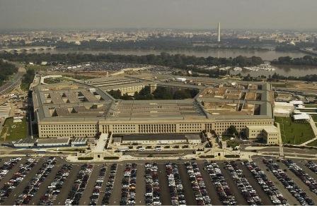
Noise key encryption combinations were originally recorded from a large mercury rectifier on a phonograph. The information was sent to users of the system. The terminal, formed by 40 blocks, weighed 50 tons, consuming 30 kW of energy. The room had to be air-cooled. The first set occupied the premises of the Pentagon building. President Franklin Roosevelt had the opportunity to communicate around the clock, listening to the plans of Prime Minister Winston Churchill, who had his own copy under Oxford Street. On July 15, 1943, the first Allied press conference took place. The parties set the required number of kits, including one that occupied the board of the flagship, General Douglas MacArthur.
Achievements
- The first secret radio communication.
- First sampled data transfer.
- Implementation of the concept of code-pulse radio channel.
- Using Compading.
- First radio transmission of multilevel frequency shift keying.
- The first speech spectrum compression technology.
- Implementation of the method of frequency division of channels using manipulation.
Development of the digital communication concept
The Canadian naval system DATAR (1949) began broadcasting information. The formation is considered the first example of a military information system, implementing the concept of a single command post. Canada well remembered 1943, when it was able to coordinate the actions of the Allied naval forces. The command decided to simplify the process. A round tablet, resembling the screen of a radar station, showed the position of the participants in the battle. The project affected the navy, along the way, experts noted the possible coverage of all branches of the military.

The 1953 demonstration failed, forcing the USAF to develop the SAGE. The central system controlled the actions of NORAD, reflecting possible attacks by the enemy air fleet. The environment, flavored with a fair share of displays, computers, has become an integral part of the Cold War. The AN/FSQ-7 supercomputer, which provided processor time to command centers, occupied 22,000 square feet of floor, formed the basis of production capacity.
The cost, estimated in the billions of dollars, outweighed the costs of the Manhattan Project. The Sky Shield test showed the interception of 25% of the bombers. Today, the control role is given to microcomputers that duplicate the functions of computer rooms. The limitations of the technology were explained by the need to use vacuum electrical devices. The military gave away some of the technology to the industry. The 24-channel machines of 1953 were far from the ocean, military aviation. The true calling of RCA technology is to send audio messages to Broad Street (New York), to keep the Rocky Point - Long Island lines functioning.
Digital revolution
The backing was ready a long time ago. The foundations painstakingly developed by scientists were laid by Charles Babbage. Communication technologies were developed by telegraphists. The United States has allocated a budget for digital projects. Claude Shannon's article The Mathematical Theory of Communication (1948) became the industry's guiding light. The industry has rushed to digitize analog signals. Copies have become identical to the original, have ceased to grow old. digital information without loss overcame the cable, the air.
1947 brought the semiconductor triode to the world. The military instantly appreciated the opportunities provided. Probably previously classified information was specially made public, assessing the potential of US civilian industry. At the same time, Japan made a great breakthrough, having lost the remnants of the feudal system. In the 1950s and 1960s, the military and the government remained the main consumers. In 1969 year Intel released the 4004 microprocessor, which prepared the basis for a future revolution. At the same time, the United States laid the foundation for the future of the global Internet network by initiating the ARPANET project.
Timeline of the development of pulse code modulation
Important! The US National Inventors Hall of Fame awarded Bernard Oliver, Claude Shannon for the creation of pulse code modulation (US patent 2.801.281, 1957).
The first broadcast transceiver system (1961) carried 24 Pulse Code Modulation (CMM) telephone channels, with a sampling rate of 8 kHz, encoded with 8-bit numbers. The communication quality corresponded to the previously used frequency multiplexing. The above helped to digitize:
- Connection. Generation 2G (1992) cellular networks became digital.
- TV broadcasting (early 90s, XX century). The Geneva Agreement, adopted on June 17, 2015, set a deadline for countries to eliminate the last signs of analogue broadcasting. The first (2006) left the Netherlands, Luxembourg. Russia plans to complete the process in 2019.
- Broadcasting (late 80s, XX century). The Norwegian corporation NRK on June 1, 1995 was the first to start commercial broadcasting. By 2017, 38 countries have launched the service, including Russia.
Invented by Alec Reeves (1937), PCM gradually reached the realm of sound recording, later taking over commercial broadcasting. The pioneers were Japanese brand products (1971) NHK, Nippon Columbia. In parallel, the experiments were carried out by the Air Force, which created a digital two-channel recorder. A year later, the British conducted a trial digital broadcast. The development of digital recording preceded the advent of broadcasting.

- The fourth generation of 4ESS switches was introduced into the US telephone line system (1976).
- Linear pulse code modulation (1982) included in the red book of CD recording standards.
- AES3, the basis of the future S/DIF, is introduced (1985).
- The .WAV file format becomes the standard personal computers (1991).
- World Recording Media Goes Digital: DVD (1995), Blu-ray (2005).
- Development of digital transmission protocols (2001) for amateur radios (D-STAR, ICOM).
- HDMI supports Pulse Code Modulation (2002).
- The RF64 container includes a CMM (2007).
Technology development summary
Kinds amateur radio brought the millennium to HF. Mentioning the developments of the Second World War, they also discussed the enormous size of the equipment (machine rooms). Minimization was in full swing, but the new items remained classified. Excluding recording areas, computer networks. The collapse of the USSR showed the world the wonders of digital technology: broadcasting, personal computing machines, connection. Gradually, the world is throwing out analog technology, modernizing equipment.

The block diagram of the process allows you to ignore aging, weather conditions, interference. The modem jokingly does the work of a World War II machine room. Radio amateurs began to allocate equipment that the Vietnamese troops dreamed of. The process will soon allow stay-at-homes to design systems while sitting in a cozy chair. Let's thank the Internet, which has given people opportunities hitherto unknown to the planet.