Hi all! I am Artem Luzhetsky and I will conduct a series of articles dedicated to " smart home"and IoT (eng. - Internet of Things, Internet of things). We will get acquainted with amazing ways to create home network from a variety of devices that will work either autonomously or with the help of a person. Well? Let's get started!
The first article is introductory, I want you to understand that I will be working with the most common boards and modules so that most people can try their hand at IoT development.
So, for starters, we need two microcontrollers that we will use: and.
Arduino UNO
I don't think I need to introduce you to this board, it's very popular among beginners and DIY enthusiasts. I will only say that the capabilities of this board are limited and UNO cannot work with the https protocol, there is not enough computing power ATmega328P microcontroller, so when we have to work with the microcontroller and the https protocol, we will program the ESP8266.
ESP8266

I will work with the Troyka-module ESP8266 from Amperka, but you can safely use the regular ESP 8266 module, they practically have no differences, the main thing when connecting is to look at the value of the pins and remember that the ESP works according to 3.3 volt logic, therefore you need to either connect through 5 volts, but connect a voltage regulator to the circuit, or simply use a pin with a voltage supply of 3.3 volts.
This microcontroller is not the most powerful in the Espressif series in the general market, but it is one of the cheapest and most common. It will be the basis of our IoT developments.
Additional details
We will also need to create all the experiments:
- LEDs
- photoresistor
- Thermistor
- ultrasonic rangefinder
- Piezo speaker
- Mini Servo
- IR sensor
- IR remote control
It is not necessary to have all these modules to work with IoT, but in order to make all future projects, we will eventually have to purchase them all.
Programs and Libraries
First - download the library which will help you to work much easier in Arduino IDE if you use ESP8266 - http://wiki.amperka.ru/_media/iot-m:iot-m-libs.zip
Secondly, to better familiarize ourselves with the IoT, we need websites that allow us to send data to them.
- www.dweet.io
- maker.iftt.com
- narodmon.ru
- etc.
Third - we will also need various applications on android so that we can control a smart home with the help of a phone.
- open hub
- Blink
- etc.
We will get acquainted with all the methods, programs and sites in detail in the next projects.
2. Making a "smart lamp"
Have I already made you bored? Let's make the simplest smart lamp which will turn on if the room is dark.
In fact, you don't even need a UNO for this, you can use a digital custom photo sensor, but in the future we will change this project beyond recognition, so you have to start somewhere.
If you are not sure that you are ready to work with electricity of 220 volts, then use a regular LED instead of a flashlight. At the beginning I took mine old lamp TLI - 204, there are such in almost any store (disconnected from the network in advance).

The lamp has two types of work (on / off), what I want to do, I want to increase its functionality, leave the ability to turn the lamp on and off completely.
Connecting a photoresistor with a relay somehow in parallel to the circuit without using another switch will not work, so I decided to put a three-position toggle switch instead of a two-position switch.

The general electrical circuit should look like this:

If everything is done correctly, then in the third position of the switch you can, by supplying current to the relay from the microcontroller, turn on the lamp.

Let's connect a photoresistor to the arduino. The schema looks like this:

3. Code for "smart lamp"

Now let's write the code by which we will transmit current to the relay if the room is dark.
#define SHINE 5 //PIN ON PHOTORESISTOR #define REL 13 //PIN ON RELAY void setup()( pinMode(SHINE, INPUT); pinMode(REL, OUTPUT); Serial.begin(9600); ) void loop()( if (analogRead(SHINE)<600) // Если света в комнате мало, то включаем лампу { digitalWrite(REL, HIGH) } else // если много, то выключаем { digitalWrite(REL, LOW); } Serial.printIn(analogRead(SHINE)); selay(500); }
When you connect everything, do not forget to remove the photo sensor from the llama, otherwise a light show will await you. Everything must work.
Next time we will try to complicate the code and add a couple more functions. See you soon!
In this experiment, the LED should turn on when the light level falls below the threshold set by the potentiometer.
LIST OF PARTS FOR THE EXPERIMENT
- 1 Arduino Uno board;
- 1 solderless breadboard;
- 1 LED;
- 1 photoresistor;
- 1 resistor with a nominal value of 220 Ohm, 1 resistor with a nominal value of 10 kOhm;
- 1 variable resistor (potentiometer);
- 10 male-male wires.
DETAILS FOR OPTIONAL OBJECTIVE
1 more LED;
Another 1 resistor with a nominal value of 220 ohms;
2 more wires.
PRINCIPAL DIAGRAM
DIAGRAM ON THE Breadboard

SKETCH
download sketch for Arduino IDE#define LED_PIN 13 #define LDR_PIN A0 #define POT_PIN A1 void setup() ( pinMode(LED_PIN, OUTPUT); ) void loop() ( // read the light level. By the way, you can // declare a variable and assign a value to it at once int lightness = analogRead(LDR_PIN); // read the value from the potentiometer with which we adjust // the threshold value between conditional darkness and light int threshold = analogRead(POT_PIN); // declare a boolean variable and assign it the value // "is it dark now". Boolean variables, unlike // integer ones, can contain only one of two values: // true (eng. true) or false (eng. false).Such values // are also called boolean (eng. boolean).boolean tooDark = (lightness< threshold); // используем ветвление программы: процессор исполнит один из // двух блоков кода в зависимости от исполнения условия. // Если (англ. «if») слишком темно... if (tooDark) { // ...включаем освещение digitalWrite(LED_PIN, HIGH); } else { // ...иначе свет не нужен — выключаем его digitalWrite(LED_PIN, LOW); } }
CODE EXPLANATIONS
- We are using a new type of variables − boolean, which only store values true (truth, 1) or false (false, 0). These values are the result of evaluating boolean expressions. In this example, the boolean expression is lightness< threshold . In human language, this sounds like: "illuminance below the threshold level." Such a statement will be true when the illumination is below the threshold level. The microcontroller can compare the values of variables lightness and threshold, which, in turn, are the results of measurements, and calculate the truth of the logical expression.
- We have taken this logical expression in brackets only for clarity. It's always better to write readable code. In other cases, parentheses can affect the order of operations, as in ordinary arithmetic.
- In our experiment, the boolean expression will be true when the value lightness less value threshold, because we used the operator < . We can use operators > , <= , >= , = = , != , which mean greater than, less than or equal to, greater than or equal to, equal to, not equal to, respectively.
- Be especially careful with logical operator = = and don't confuse it with the assignment operator = . In the first case, we compare the values of the expressions and get boolean(true or false), and in the second case, we assign the value of the right operand to the left operand. The compiler does not know our intentions and will not give an error, but we can accidentally change the value of some variable and then look for an error for a long time.
- Conditional operator if (« if”) is one of the key ones in most programming languages. With its help, we can perform not only a rigidly defined sequence of actions, but make decisions on which branch of the algorithm to follow, depending on certain conditions.
- For a logical expression lightness< threshold there is a meaning: true or false. We calculated it and put it in a boolean variable tooDark("too dark"). Thus, we kind of say "if it's too dark, then turn on the LED"
- We could just as well say "if the illumination is less than the threshold level, then turn on the LED", i.e. transfer to if the whole logical expression:
if (lightness< threshold) { // ... }
- Per conditional operator if must be followed by a block of code that is executed if the logical expression is true. Don't forget about both curly braces {} !
- If, if the expression is true, we only need to execute one instruction, it can be written immediately after if(...) without curly braces:
if (lightness< threshold) digitalWrite(LED_PIN, HIGH);
- Operator if can be extended by design else("otherwise"). The block of code, or the single statement following it, will only be executed if the boolean expression in if has the meaning false , « False". The rules for curly braces are the same. In our experiment, we wrote "if it's too dark, turn on the LED, otherwise turn off the LED."
QUESTIONS TO CHECK YOURSELF
- If we install a photoresistor between the analog input and ground, our device will work in reverse: the LED will turn on when the amount of light increases. Why?
- What result of the operation of the device will we get if the light from the LED falls on the photoresistor?
- If we did install the photoresistor as described in the previous question, how do we need to change the program so that the device works correctly?
- Let's say we have a code if (condition) (action;). In what cases will action ?
- At what values y expression x + y > 0 will be true if x > 0 ?
- Is it mandatory to specify which instructions to execute if the condition in the statement if false?
- What is the difference between operator = = from the operator = ?
- If we use the construction if (condition) action1; else action2;, can there be a situation where none of the actions will be executed? Why?
TASKS FOR INDEPENDENT SOLUTION
- Rewrite the program without using a variable tooDark while maintaining the functionality of the device.
- Add another LED to the circuit. Complete the program so that when the illumination falls below the threshold value, one LED turns on, and when the illumination falls below half the threshold value, both LEDs turn on.
- Change the circuit and program so that the LEDs turn on in the same way, but glow the stronger, the less light falls on the photoresistor.
Probably, everyone in childhood had a dream (and more than one). You can even try to remember the feeling that overwhelms the soul of a child when his dream comes true, or that distant familiar sparkle in his eyes ... As a child, I dreamed of having my own night light.
Now I am a 4th year student at BSUIR, and when we were told that a course project on circuitry can be done not on paper, but on a piece of iron, it dawned on me: the night light, which I so desired as a child, can be made by myself. And to make not just an object that will illuminate the room at night, but a device that can be easily controlled for any mood. Why not? I decided to add the ability to change colors with the help of hands: the closer the hand is brought to the night light, the brighter one of the colors (RGB) burns. And also I would like to control the night light with the remote control.
I must admit right away that I spied the idea on the site cxem.net. In short, this example used an RGB matrix that was controlled by shift registers and ultrasonic distance sensors. But I thought that the matrix shines only in one direction, but I wanted the nightlight to shine on the sides.
Justification of the circuit elements
 I turned my attention to Arduino microcontrollers. UNO is quite a suitable option for my idea, firstly because it is the most popular platform and the number of pins is not too large, unlike Mega, and secondly, you can connect an external power source to it, in my case it is 12V, unlike Nano , thirdly ... well, I think you can dwell on these two points. The platform is very popular all over the world due to the convenience and simplicity of the programming language, as well as open architecture and program code.
 More detailed information about this board can be easily found on the Internet, so I will not overload the article.
So, the main requirements for the system. Required:
- sensors that will track the distance to the obstacle to control the system;
– sensor for reading signals from the remote control remote control;
- LEDs, which will provide the necessary lighting functionality;
- a control unit that will control the entire system.

As distance sensors for the project, rangefinders are needed, each of which will correspond to certain color: red, green, blue. Distance sensors will monitor the distance of the hand from the nightlight and the closer the hand is brought to a certain sensor, the stronger the color corresponding to this rangefinder will burn. Conversely, the farther the hand is, the less voltage is applied to the color corresponding to the sensor.
The most popular rangefinders on this moment these are Sharp GP2Y0A21YK and HC-SR04. Sharp GP2Y0A21YK is an infrared rangefinder. It is equipped with an IR emitter and an IR receiver: the first serves as a source of a beam, the reflection of which catches the second. At the same time, the infrared rays of the sensor are invisible to the human eye and are harmless at this intensity.
Compared with the HC-SR04 ultrasonic transducer, this transducer has both advantages and disadvantages. The advantages include neutrality and harmlessness. And the disadvantages are a smaller range and dependence on external interference, including certain types of lighting.
 As distance sensors for the project, we used ultrasonic rangefinders HC-SR04.
The principle of operation of the HC-SR04 is based on the well-known phenomenon of echolocation. When it is used, the emitter generates an acoustic signal, which, reflected from the obstacle, returns to the sensor and is recorded by the receiver. Knowing the speed of propagation of ultrasound in the air (about 340 m/s) and the delay time between the emitted and received signal, it is easy to calculate the distance to the acoustic barrier.
The TRIG input is connected to any pin of the microcontroller. A pulse must be applied to this output. digital signal duration 10 µs. On a signal at the TRIG input, the sensor sends a burst of ultrasonic pulses. After receiving the reflected signal, the sensor generates a pulse signal at the ECHO output, the duration of which is proportional to the distance to the obstacle.
 IR sensor. Of course, the signal needed for remote control will be read and decoded from this sensor. TSOP18 differ only in frequency. The VS1838B TSOP1838 sensor is selected for the project.
The project was based on the idea of lighting the room with any color, which means that 3 primary colors will be needed from which the lighting will be obtained: red, green, blue. Therefore, the SMD 5050RGB LED model was chosen, which will perfectly cope with the task.
Depending on the amount of voltage applied to each LED, they will change the intensity of this illumination. The LED must be connected through a resistor, otherwise we risk ruining not only it, but also the Arduino. The resistor is needed in order to limit the current on the LED to an acceptable value. The fact is that the internal resistance of the LED is very low and, if you do not use a resistor, then such a current will pass through the LED, which will simply burn both the LED and the controller.
 The LED strips used in the project are powered by 12V.
Due to the fact that the voltage on the LEDs in the “off” state is 6V and it is necessary to regulate the power supply, which exceeds 5V, it is necessary to add transistors in the key mode to the circuit. My choice fell on the BC547c model.
Consider briefly, for those who have forgotten, the principle of operation npn transistor. If you do not apply voltage at all, but simply take and close the terminals of the base and emitter, even if not for a short time, but through a resistor of several ohms, it turns out that the base-emitter voltage is zero. Therefore, there is no base current. The transistor is closed, the collector current is negligible, just the same initial current. In this case, the transistor is said to be in the cutoff state. The opposite state is called saturation: when the transistor is fully open, so that there is nowhere to open further. With such a degree of opening, the resistance of the collector-emitter section is so small that it is simply impossible to turn on the transistor without a load in the collector circuit, it will burn out instantly. In this case, the residual voltage on the collector can be only 0.3 ... 0.5V.
These two states, saturation and cutoff, are used when the transistor operates in the key mode, like a normal relay contact. The main meaning of this mode is that a small base current controls a large collector current, which is several tens of times greater than the base current. A large collector current is obtained due to an external energy source, but still, current amplification, as they say, is evident. In our case, a microcircuit whose operating voltage is 5V includes 3 strips with LEDs operating from 12V.
Let us calculate the operating mode of the key cascade. It is required to calculate the value of the resistor in the base circuit so that the LEDs burn at full power. A necessary condition in the calculation that the current gain is greater than or equal to the quotient of dividing the maximum possible collector current by the minimum possible base current:
Therefore, the strips can be for an operating voltage of 220V, and the base circuit can be controlled from a microcircuit with a voltage of 5V. If the transistor is designed to work with this collector voltage, then the LEDs will light up without problems.
The voltage drop at the base-emitter junction is 0.77V, provided that the base current is 5mA, the collector current is 0.1A.
The voltage across the base resistor will be:
Ohm's Law: 
From the standard series of resistances, we select a resistor of 8.2 kOhm. This completes the calculation.
I want to draw your attention to one problem that I encountered. When using the IRremote library, the Arduino would hang when adjusting the blue color. After a long and careful search on the Internet, it turned out that given library uses the default timer 2 for this Arduino model. Timers are used to control PWM outputs.
Timer 0 (System time, PWM 5 and 6);
Timer 1 (PWM 9 and 10);
Timer 2 (PWM 3 and 11).
Initially, I used PWM 11 to regulate blue. Therefore, be careful when working with PWM, timers and third-party libraries that can use them. It's strange that on home page On the github, nothing was said about this nuance. If you wish, you can uncomment the line with timer 1 and comment out 2.
Connecting elements on the breadboard looks like this:

After testing on a breadboard, the phases "Placing elements on the board" and "Working with a soldering iron" began. After the first testing of the finished board, the thought creeps into my head: something went wrong. And here the familiar to many phase “Painstaking work with the tester” begins. However, the malfunctions (several adjacent contacts were accidentally soldered) were quickly eliminated and here it is the long-awaited mischievous LED light.

Further, the matter was only behind the body. On this occasion, plywood with holes for our sensors was cut. The back cover was made specially removable so that you can enjoy the view from the inside and, if desired, finish or redo something. It also has 2 holes for reprogramming the board and power.
The case was glued on a two-component epoxy glue. It is worth noting the peculiarity of this glue, for those who have not met with it before. This comrade is supplied in two separate containers, when the contents of which are mixed, an instant chemical reaction occurs. After mixing, you have to act quickly, within 3-4 minutes. For further use, you need to mix a new portion. So if you are trying to repeat this, my advice to you is to mix in small portions and act very quickly, there will not be much time to think. Therefore, it is worth considering in advance how and where to glue the case. And it can't be done in one sitting.
For fixing strips with LEDs in top cover a tube was inserted through which all the wires passed perfectly.

When the question arose with the lampshade, I remembered how in my childhood I made crafts from a simple thread, glue and a balloon, which served as the basis. The principle for the lampshade was taken the same, but it turned out to be more difficult to wind the polyhedron than the ball. Due to the pressure exerted by the threads on the structure, it began to narrow upwards and the threads began to fall off. Urgently, with hands in glue, it was decided to strengthen the structure from above. And then the CD came to the rescue. The end result is this nightlight:

What do you want to say in the end?
What should I change in the project? To supply the TRIG signal of the distance sensors, one Arduino output could be used instead of three. I would also provide a hole for the IR sensor (which I forgot about), which, alas, is hidden in the case from which, of course, it cannot read signals from the remote control. However, who said that you can not solder and drill anything?
I would like to note that it was an interesting semester, and a great opportunity to try to do something not on paper, thanks to which I can put one more check mark next to the “childhood dream” item. And if it seems to you that trying something new is difficult, and you don’t know what to do first, don’t worry. Many people have a thought in their heads: where to start here and how can this be done at all? In life, there are many tasks from which you can get confused, but once you try, you will notice that with a twinkle in your eyes you can move mountains, even if you have to try a little for this.
Light sensors (lighting), built on the basis of photoresistors, are quite often used in real arduino projects. They are relatively simple, not expensive, easy to find and buy in any online store. The arduino photoresistor allows you to control the level of illumination and respond to its change. In this article, we will look at what a photoresistor is, how the light sensor works based on it, how to properly connect the sensor to the Arduino boards.
The photoresistor, as the name suggests, is directly related to resistors, which are often found in almost any electronic circuit. The main characteristic of a conventional resistor is the value of its resistance. Voltage and current depend on it, with the help of a resistor we set the desired operating modes of other components. As a rule, the value of the resistance of a resistor under the same operating conditions practically does not change.
 Unlike a conventional resistor, photoresistor can change its resistance depending on the level of ambient light. This means that in electronic circuit parameters will constantly change, first of all we are interested in the voltage falling on the photoresistor. By fixing these voltage changes on the analog pins of the arduino, we can change the logic of the circuit, thereby creating devices that adapt to the external conditions.
 Photoresistors are widely used in a wide variety of systems. The most common application is street lighting. If night falls on the city or it becomes cloudy, the lights turn on automatically. You can make an economical light bulb for the home out of a photoresistor, which turns on not according to a schedule, but depending on the lighting. Based on the light sensor, you can even make security system, which will be triggered immediately after a closed cabinet or safe is opened and lit. As always, the scope of any arduino sensors is limited only by our imagination.
What photoresistors can be bought in online stores
The most popular and affordable sensor option on the market is the mass production models of Chinese companies, clones of VT products. It is not always possible to go broke there, who and what exactly this or that supplier produces, but the simplest option is quite suitable to start working with photoresistors.

A novice arduinist can be advised to buy a ready-made photo module that looks like this:


This module already has all the necessary elements for easily connecting a photoresistor to an arduino board. In some modules, a comparator circuit is implemented and a digital output and a trimmer for control are available.
A Russian radio amateur can be advised to turn to the Russian FR sensor. Commercially available FR1-3, FR1-4, etc. - issued back in Soviet times. But, despite this, FR1-3 is a more accurate detail. From this follows the difference in price. For FR they ask no more than 400 rubles. FR1-3 will cost more than a thousand rubles apiece.
Photoresistor marking
Modern marking of models produced in Russia is quite simple. The first two letters are PhotoResistor, the numbers after the dash indicate the development number. FR -765 - photoresistor, development 765. Usually marked directly on the part body
The VT sensor has a resistance range in the marking scheme. For example:
- VT83N1 - 12-100kΩ (12K illuminated, 100K dark)
- VT93N2 - 48-500kOhm (48K - illuminated, 100K - in the dark).

Sometimes, to clarify information about models, the seller provides a special document from the manufacturer. In addition to the parameters of work, the accuracy of the part is also indicated there. For all models, the sensitivity range is located in the visible part of the spectrum. Collecting light sensor you need to understand that the accuracy of operation is a conditional concept. Even for models of the same manufacturer, one batch, one purchase, it can differ by 50% or more.
At the factory, the parts are set to a wavelength from red to green light. At the same time, the majority “sees” and infrared radiation. Particularly precise details can capture even ultraviolet light.
Advantages and disadvantages of the sensor
The main disadvantage of photoresistors is their sensitivity to the spectrum. Depending on the type of incident light, the resistance can vary by several orders of magnitude. The cons also include low speed reactions to changes in illumination. If the light blinks, the sensor does not have time to respond. If the frequency of change is quite high, the resistor will generally stop "seeing" that the illumination is changing.
The advantages include simplicity and accessibility. A direct change in resistance depending on the light falling on it allows you to simplify wiring diagram connections. The photoresistor itself is very cheap, it is included in numerous arduino kits and designers, therefore it is available to almost any novice arduino.
Connecting photoresistor to arduino
In projects arduino The photoresistor is used as a light sensor. Receiving information from it, the board can turn relays on or off, start engines, send messages. Naturally, in this case, we must correctly connect the sensor.
The scheme for connecting a light sensor to an arduino is quite simple. If we use a photoresistor, then in the connection diagram the sensor is implemented as a voltage divider. One shoulder changes from the level of illumination, the second - supplies voltage to the analog input. In the controller chip, this voltage is converted into digital data through the ADC. Because If the resistance of the sensor decreases when light hits it, then the value of the voltage falling on it will also decrease.

Depending on which arm of the divider we put the photoresistor, either increased or reduced voltage will be applied to the analog input. In the event that one leg of the photoresistor is connected to the ground, then the maximum voltage value will correspond to darkness (the resistance of the photoresistor is maximum, almost all the voltage drops across it), and the minimum value will correspond to good lighting (resistance is close to zero, the voltage is minimal). If we connect the photoresistor arm to power, then the behavior will be the opposite.
The installation of the board itself should not cause difficulties. Since the photoresistor has no polarity, you can connect it in any direction, you can solder it to the board, connect it with wires using a circuit board, or use ordinary clips (crocodiles) for connection. The power source in the circuit is the arduino itself. photoresistor is connected with one leg to the ground, the other is connected to the ADC of the board (in our example - AO). We connect a 10 kΩ resistor to the same leg. Naturally, you can connect a photoresistor not only to the analog pin A0, but also to any other.
A few words about the additional 10K resistor. It has two functions in our circuit: to limit the current in the circuit and to form the right voltage in a circuit with a divider. Current limitation is needed in a situation where a fully illuminated photoresistor sharply reduces its resistance. And voltage shaping is for predictable values on the analog port. In fact, 1K resistance is enough for normal operation with our photoresistors.
By changing the value of the resistor, we can “shift” the sensitivity level to the “dark” and “light” side. So, 10 K will give fast switching the coming of the world. In the case of 1K, the light sensor will more accurately detect a high level of illumination.
If you use a ready-made light sensor module, then the connection will be even easier. We connect the output of the VCC module to the 5V connector on the board, GND - to ground. The remaining pins are connected to the arduino connectors.
If the board has a digital output, then we send it to the digital pins. If analog, then analog. In the first case, we will receive a trigger signal - exceeding the illumination level (the trigger threshold can be adjusted using a tuning resistor). From the analog pins, we can get a voltage value proportional to the actual level of illumination.
An example sketch of a light sensor on a photoresistor
We connected the photoresistor circuit to the arduino, making sure that everything was done correctly. Now it remains to program the controller.
Writing a sketch for a light sensor is quite simple. We only need to take the current voltage value from the analog pin to which the sensor is connected. This is done using the analogRead() function known to all of us. Then we can perform some actions, depending on the light level.
Let's write a sketch for a light sensor that turns on or off the LED connected as follows.

The algorithm of work is as follows:
- Determine the level of the signal from the analog pin.
- Compare the level with the threshold value. The maximum value will correspond to the darkness, the minimum - to the maximum illumination. Let's choose the threshold value equal to 300.
- If the level is less than the threshold - dark, you need to turn on the LED.
- Otherwise, turn off the LED.
By covering the photoresistor (with hands or an opaque object), we can observe the on and off of the LED. By changing the threshold parameter in the code, we can force the light bulb to turn on / off when different levels lighting.
When mounting, try to place the photoresistor and the LED as far apart as possible so that less light from the bright LED falls on the light sensor.
Ambient light sensor and smooth change of backlight brightness
You can modify the project so that the brightness of the LED changes depending on the level of illumination. We will add the following changes to the algorithm:
- We will change the brightness of the light bulb through PWM, sending values from 0 to 255 to the pin with the LED using analogWrite ().
- To convert the digital value of the light level from the light sensor (from 0 to 1023) into the PWM range of the LED brightness (from 0 to 255), we will use the map() function.
Sketch example:
#define PIN_LED 10 #define PIN_PHOTO_SENSOR A0 void setup() ( Serial.begin(9600); pinMode(PIN_LED, OUTPUT); ) void loop() ( int val = analogRead(PIN_PHOTO_SENSOR); Serial.println(val); int ledPower = map(val, 0, 1023, 0, 255); // Convert the received value into a PWM signal level. The smaller the light value, the less power we need to supply to the LED via PWM. analogWrite(PIN_LED, ledPower); // change brightness)
In the case of another connection method, in which the signal from the analog port is proportional to the degree of illumination, it will be necessary to additionally “reverse” the value by subtracting it from the maximum:
int val = 1023 - analogRead(PIN_PHOTO_RESISTOR);
Scheme of the light sensor on the photoresistor and relay
Examples of a sketch for working with relays are given in the article on programming relays in arduino. In this case, we do not need to make complex gestures: after determining “darkness”, we simply turn on the relay, apply the appropriate value to its pin.
#define PIN_RELAY 10 #define PIN_PHOTO_SENSOR A0 void setup() ( pinMode(PIN_RELAY, OUTPUT); digitalWrite(PIN_RELAY, HIGH); ) void loop() ( int val = analogRead(PIN_PHOTO_SENSOR); if (val< 300) { // Светло, выключаем реле digitalWrite(PIN_RELAY, HIGH); } else { // Темновато, включаем лампочку digitalWrite(PIN_RELAY, LOW); } }
Conclusion
Projects using a light sensor based on a photoresistor are quite simple and effective. You can implement many interesting projects, while the cost of equipment will not be high. The photoresistor is connected according to the voltage divider circuit with additional resistance. The sensor is connected to an analog port to measure various levels of illumination or to a digital one if only the fact of darkness is important to us. In the sketch, we simply read data from the analog (or digital) port and decide how to react to changes. Let's hope that now such simple "eyes" will appear in your projects.
For our next project, we will be using a photoresistor. And we will consider the implementation of a night light in the bedroom, which will automatically turn on when it is dark and turn off when it becomes light.
The resistance of a photoresistor depends on the light hitting it. Using a photoresistor in conjunction with conventional resistor 4.7 kOhm, we get a voltage divider in which the voltage passing through the photoresistor changes, depending on the level of illumination.
The voltage from the divider, we apply to the Arduino ADC input. There we compare the received value with a certain threshold and turn the lamp on or off.
The circuit diagram of the divider is shown below. When the illumination increases, the resistance of the photoresistor drops and, accordingly, the voltage at the output of the divider (and the input of the ADC) increases. When the light goes down, the opposite is true.

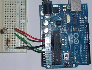
The photo below shows assembled circuit on the breadboard. The 0V and 5V voltages are taken from the Arduino. Pin A0 is used as an ADC input.
The Arduino sketch is shown below. In this tutorial, we simply turn on and off the LED that is built into the Arduino board. A brighter LED, you can connect to pin 13 (through a ~220 ohm resistor). If you connect a more powerful load, such as an incandescent lamp, then it should be connected through a relay or thyristor.
There are commented sections in the program code, they serve for debugging. It will be possible to control the ADC value (from 0 to 1024). Also, it is necessary to change the value of 500 in the code (threshold on and off) to the one that you select empirically by changing the illumination.
/* ** Night light ** ** www.hobbytronics.co.uk */ int sensorPin = A0; // set input foot for ADC unsigned int sensorValue = 0; // digital value photoresistor void setup() ( pinMode(13, OUTPUT); Serial.begin(9600); // start serial data output (for testing) ) void loop() ( sensorValue = analogRead(sensorPin); // read value from photoresistor if (sensorValue<500) digitalWrite(13, HIGH); // включаем else digitalWrite(13, LOW); // выключаем // Для отладки раскомментируйте нижеследующие строки //Serial.print(sensorValue, DEC); // вывод данных с фоторезистора (0-1024) //Serial.println(""); // возврат каретки //delay(500); }